


Introduction: Architectural Context for Healthcare Scheduling
In the rapidly evolving landscape of digital health, the efficiency of appointment scheduling directly impacts patient satisfaction and operational throughput. A Hospital Management System (HMS) must handle complex logic involving multiple stakeholders: patients seeking care, receptionists managing front-desk logistics, and medical staff whose availability dictates service delivery. Visualizing these interactions is not merely about drawing boxes; it is about defining the temporal logic and data flow that keeps a healthcare facility running.

Diagramming-as-code with PlantUML offers a distinct advantage for software architects and developers. Unlike traditional drag-and-drop tools, writing code allows for versioning of the logic itself, easier collaboration, and instant iteration. By using VPasCode, a free web-based diagram-as-code editor, teams can prototype these critical workflows without installing local dependencies. This tutorial demonstrates how to construct a professional sequence diagram that models the appointment scheduling scenario, highlighting normal flows, alternative scenarios, and system boundaries.
Understanding the Model: Purpose, Scope & Problem Framing
Before diving into the syntax, it is essential to understand what this specific model represents and why it is the appropriate tool for the job.
Diagram Abstraction & Representation
A sequence diagram is the ideal choice for modeling the interaction between system components over time. In this healthcare context, it answers critical questions: Who initiates the request? How does the system validate doctor availability? What happens when a conflict arises? The diagram captures the chronological exchange of messages (synchronous and asynchronous) between actors and objects, providing a clear view of the runtime behavior.
Target Domain Scope & Scenario
This model focuses specifically on the Appointment Scheduling module of an HMS. It intentionally excludes other workflows like billing or patient records to maintain clarity. The scope includes:
- Actors: The Patient (initiator) and Receptionist (facilitator).
- System: The HMS backend logic.
- Resources: The Doctor entity whose schedule is queried.
- Logic: Availability checks, slot reservation, and cancellation handling.
Key Takeaways & Educational Insights
By building this diagram, readers will gain:
- Clarity on how to model conditional logic (if/else) using combined fragments.
- Understanding of activation bars to show when an object is actively processing.
- Best practices for naming actors and participants to reflect real-world roles.
Complete Diagram & Full Source Code
Below is the finalized blueprint for the Hospital Management System Appointment Scheduling Sequence Diagram. You can view the rendered result immediately by pasting the code into the VPasCode editor.
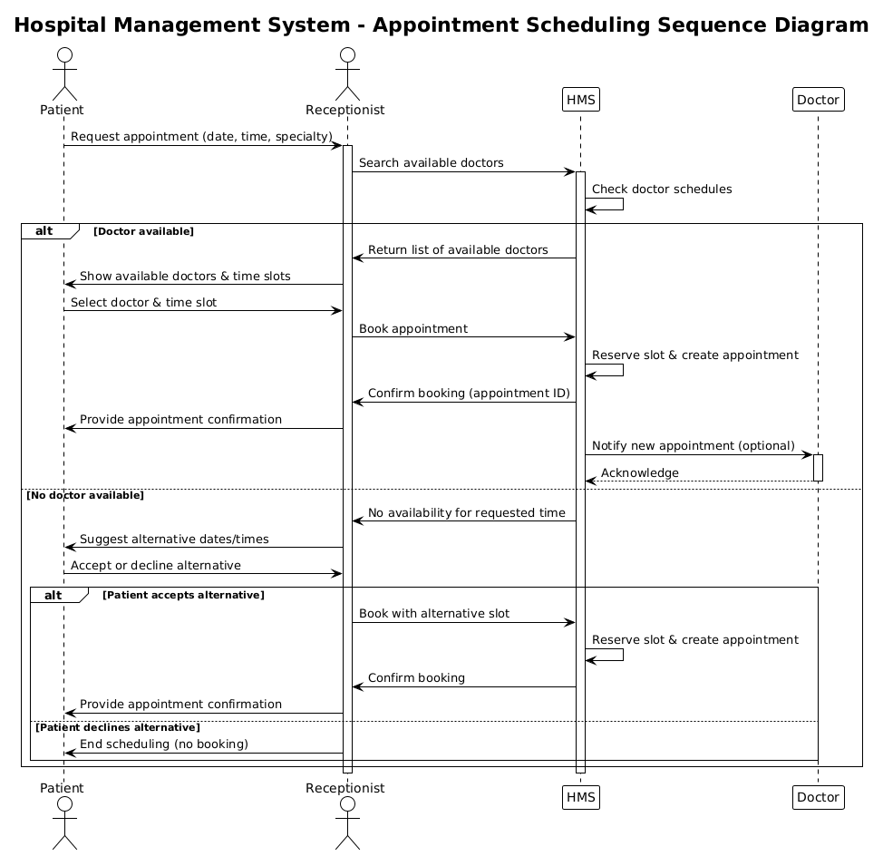
@startuml

!theme plain
title Hospital Management System - Appointment Scheduling Sequence Diagram

/'
This sequence diagram illustrates the appointment scheduling process in a Hospital Management System.
It covers the normal flow where a patient requests an appointment and the system checks doctor availability.
Alternative flows are included for when the doctor is unavailable or when the patient cancels the request.
Actors involved: Patient, Receptionist, HMS (Hospital Management System), and Doctor.
'/

actor "Patient" as P
actor "Receptionist" as R
participant "HMS" as HMS
participant "Doctor" as D

P -> R: Request appointment (date, time, specialty)
activate R

R -> HMS: Search available doctors
activate HMS

HMS -> HMS: Check doctor schedules

alt Doctor available
    HMS -> R: Return list of available doctors
    R -> P: Show available doctors & time slots
    P -> R: Select doctor & time slot
    R -> HMS: Book appointment
    HMS -> HMS: Reserve slot & create appointment
    HMS -> R: Confirm booking (appointment ID)
    R -> P: Provide appointment confirmation
    HMS -> D: Notify new appointment (optional)
    activate D
    D --> HMS: Acknowledge
    deactivate D

else No doctor available
    HMS -> R: No availability for requested time
    R -> P: Suggest alternative dates/times
    P -> R: Accept or decline alternative
    alt Patient accepts alternative
        R -> HMS: Book with alternative slot
        HMS -> HMS: Reserve slot & create appointment
        HMS -> R: Confirm booking
        R -> P: Provide appointment confirmation
    else Patient declines alternative
        R -> P: End scheduling (no booking)
    end
end

deactivate HMS
deactivate R

@endumlStep-by-Step Architectural Walkthrough
Building a robust sequence diagram requires a structured approach. We will walk through the construction of this Healthcare Scheduling model in four distinct phases.
Phase 1: Canvas Configuration & Layout Directives
Every PlantUML diagram begins with setup. We define the theme to ensure consistency and add metadata for clarity. The !theme plain directive ensures a clean, standard look that works well in technical documentation. We also include a title and a comment block.
!theme plain
title Hospital Management System - Appointment Scheduling Sequence Diagram

/'
This sequence diagram illustrates the appointment scheduling process...
'/
The comment block (starting with /' and ending with '/) is crucial for documentation. It allows future maintainers to understand the scope without reading the entire logic.
Phase 2: Declaring Core Entities, Actors, and Boundaries
Next, we define the participants. In PlantUML, actor represents human users, while participant represents system components or data objects. Clear naming conventions help distinguish between the external user and the internal system logic.
actor "Patient" as P
actor "Receptionist" as R
participant "HMS" as HMS
participant "Doctor" as D
Here, we use aliases (P, R, HMS, D) to keep the message labels concise later in the diagram. This reduces visual clutter while maintaining semantic meaning.
Phase 3: Mapping Data Flows & Key Interactions
This is the core of the sequence diagram. We use solid arrows (->) for synchronous messages and dashed arrows (-->) for return messages. We also introduce the alt (alternative) combined fragment to handle conditional logic, such as checking doctor availability.
P -> R: Request appointment (date, time, specialty)
activate R

R -> HMS: Search available doctors
activate HMS

alt Doctor available
    HMS -> R: Return list of available doctors
    ...
else No doctor available
    ...
end
The activate directive is placed immediately after a message is sent to indicate that the receiving object is processing. This visual cue is vital for understanding system load and processing time.
Phase 4: Grouping, Annotations & Visual Polish
Finally, we ensure all processes are properly closed. Every activate should ideally have a corresponding deactivate to show when an object returns to an idle state. We also handle nested logic, such as the patient’s decision to accept an alternative slot within the else block.
deactivate HMS
deactivate R
Closing the frames ensures the diagram renders cleanly and accurately reflects the lifecycle of the interaction.
Syntax & Keyword Deep Dive
To master this diagram, you must understand the specific PlantUML keywords used. Below is a breakdown of the critical syntax elements.
actor: Defines a human participant (e.g., Patient, Receptionist) interacting with the system.participant: Defines a system component, object, or class (e.g., HMS, Doctor).->: Represents a synchronous message or request sent from one object to another.-->: Represents an asynchronous message or a return response.activate/deactivate: Controls the vertical activation bar on a lifeline, indicating when an object is busy.alt/else/end: Creates a combined fragment box to represent conditional logic (if/else).title: Sets the main heading of the diagram.
Best Practices & Pitfalls to Avoid
When modeling complex healthcare workflows, adhere to these guidelines to maintain diagram quality:
- Keep Diagrams Modular: Do not try to model the entire Hospital Management System in one sequence diagram. Focus on specific use cases like “Appointment Scheduling” or “Billing” separately.
- Manage Visual Complexity: If an
altblock becomes too deep, consider breaking it into a separate diagram. Deep nesting makes the flow hard to read. - Consistent Naming: Use consistent aliases (P, R, HMS) throughout the diagram to avoid confusion.
- Clear Message Labels: Ensure message labels describe the intent (e.g., “Book appointment”) rather than just the data (e.g., “POST /api/book”).
Try It Yourself with VPasCode
Start Building PlantUML Sequence Diagrams Faster with VPasCode
Instantly render and customize your Hospital Management System workflow diagrams online without installing any tools or configuring local environments.