


Introduction & System Overview
Designing a Credit Card Processing System requires clear visualization of complex financial workflows. In the finance industry, understanding how actors interact with the core system is critical for security and compliance. This tutorial demonstrates how to build a professional Use Case diagram using VPasCode, our free PlantUML editor.

Complete Diagram & Full Source Code
Below is the finished diagram illustrating the Credit Card Processing System. You can view the visual representation below and access the complete source code for immediate use.
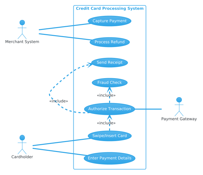
@startuml
!theme cerulean

left to right direction

actor "Cardholder" as Customer
actor "Merchant System" as Merchant
actor "Payment Gateway" as Gateway

rectangle "Credit Card Processing System" {
    usecase "Swipe/Insert Card" as UC_Swipe
    usecase "Enter Payment Details" as UC_EnterDetails
    usecase "Authorize Transaction" as UC_Authorize
    usecase "Capture Payment" as UC_Capture
    usecase "Process Refund" as UC_Refund
    usecase "Fraud Check" as UC_Fraud
    usecase "Send Receipt" as UC_Receipt
}

Customer -- UC_Swipe
Customer -- UC_EnterDetails

Merchant -- UC_Capture
Merchant -- UC_Refund

UC_Swipe .> UC_Authorize : <<include>>
UC_EnterDetails .> UC_Authorize : <<include>>

UC_Authorize -- Gateway

UC_Authorize .> UC_Fraud : <<include>>
UC_Authorize .> UC_Receipt : <<include>>

@endumlStep-by-Step Breakdown & Thought Process
I start by setting up the foundational structure to ensure the diagram renders with the desired aesthetic and orientation.
!theme cerulean
left to right direction
Next, I define the core entities and components. In a financial context, identifying the external actors is the first step in modeling system boundaries.
actor "Cardholder" as Customer
actor "Merchant System" as Merchant
actor "Payment Gateway" as Gateway
To connect everything, I map out the relationships. Use the rectangle directive to group the internal use cases within the system boundary.
rectangle "Credit Card Processing System" {
    usecase "Swipe/Insert Card" as UC_Swipe
    usecase "Authorize Transaction" as UC_Authorize
}
Finally, I refine the layout and styling. Using <<include>> relationships helps reduce clutter by showing that authorization is a prerequisite for other actions.
UC_Swipe .> UC_Authorize : <>
Key Takeaways & Best Practices
- Use System Boundaries: Always encapsulate internal processes within a rectangle to clearly distinguish system behavior from external actors.
- Leverage <<include>>: Use include relationships for mandatory sub-processes to keep your diagram clean and logical.
- Choose the Right Theme: Apply themes like
ceruleanto match your organization’s branding or improve readability.
Try It Yourself with VPasCode
Ready to start modeling your own diagrams? Experience the power of diagram-as-code with VPasCode.
VPasCode Editor (Free to use): https://vpascode.com/editor
VPasCode Home Page: https://vpascode.com/