


Architecting Trust: The Role of Sequence Diagrams in InsurTech Payment Flows
In the rapidly evolving InsurTech landscape, reliability is not just a feature—it is the foundation of customer trust. When a policyholder initiates a premium payment, the system must orchestrate complex interactions between customer portals, third-party payment gateways, and internal policy administration databases. A single misstep in this flow can lead to coverage gaps, financial discrepancies, or compliance violations.

This is where PlantUML shines as a diagram-as-code tool. By modeling these interactions visually before writing a single line of production code, architects can validate the temporal logic of their system. Using VPasCode, the free web-based PlantUML editor, you can instantly render these diagrams to ensure every actor—from the Policy Holder to the Payment Provider—communicates correctly.
In this masterclass, we will construct a professional-grade sequence diagram for an Insurance Premium Payment scenario. We will focus on capturing both the happy path (successful payment) and the alternative flow (payment failure), ensuring your documentation is as resilient as the software you build.
Understanding the Model: Purpose, Scope & Problem Framing
Diagram Abstraction & Representation
A sequence diagram is the ideal tool for modeling the dynamic behavior of a system over time. Unlike class diagrams that show static structure, sequence diagrams answer the question: “What happens when, and in what order?” In this specific financial scenario, the diagram abstracts the runtime messaging between components. It visualizes the lifecycle of a payment request, showing how data flows from the user interface, through the payment processor, and into the core administrative database.
Key Modeling Elements:
- Lifelines: Represent the persistent participants (e.g., Policy Holder, Payment Service) that exist throughout the transaction.
- Activation Bars: Indicate periods during which a participant is actively processing a request, helping identify bottlenecks or long-running operations.
- Combined Fragments: The
altblock is crucial here to explicitly define the decision logic where the system branches based on the success or failure of the external payment gateway.
Target Domain Scope & Scenario
This diagram focuses strictly on the premium payment lifecycle. It excludes unrelated flows like policy renewal reminders or claim submissions to maintain clarity. The scope covers the interaction boundaries between the external-facing Insurance Portal and the backend Policy Administration System (PAS), mediated by a Payment Service and an external Payment Provider.
Key Takeaways & Educational Insights
By building this diagram, you will gain clarity on:
- Boundary Management: How to clearly distinguish between internal services (Payment Service) and external dependencies (Payment Provider).
- Error Handling: How to model negative outcomes (e.g., insufficient funds) without cluttering the primary success path.
- State Updates: How to visualize the final state change, where the Premium Records database is updated only after successful payment confirmation.
Complete Diagram & Full Source Code
Below is the complete blueprint for the Insurance Premium Payment flow. You can view the rendered result and edit the code directly in the VPasCode editor.
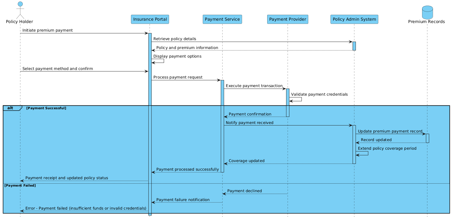
Note: The image placeholder above represents the rendered output. To see the live diagram, use the interactive code block below.
@startuml
!include https://static.visual-paradigm.com/web/resources/plantuml-stdlib/themes/vp.puml

actor "Policy Holder" as PH
participant "Insurance Portal" as IP
participant "Payment Service" as PS
participant "Payment Provider" as PP
participant "Policy Admin System" as PAS
database "Premium Records" as PR

PH -> IP: Initiate premium payment
activate IP
IP -> PAS: Retrieve policy details
activate PAS
PAS --> IP: Policy and premium information
deactivate PAS

IP -> IP: Display payment options
PH -> IP: Select payment method and confirm
IP -> PS: Process payment request
activate PS

PS -> PP: Execute payment transaction
activate PP
PP -> PP: Validate payment credentials

alt Payment Successful
    PP --> PS: Payment confirmation
    deactivate PP

    PS -> PAS: Notify payment received
    activate PAS
    PAS -> PR: Update premium payment record
    activate PR
    PR --> PAS: Record updated
    deactivate PR

    PAS -> PAS: Extend policy coverage period
    PAS --> PS: Coverage updated
    deactivate PAS

    PS --> IP: Payment processed successfully
    deactivate PS

    IP --> PH: Payment receipt and updated policy status
else Payment Failed
    PP --> PS: Payment declined
    deactivate PP

    PS --> IP: Payment failure notification
    deactivate PS

    IP --> PH: Error - Payment failed (insufficient funds or invalid credentials)
end

deactivate IP
@endumlStep-by-Step Architectural Walkthrough
Let’s deconstruct how this diagram was constructed, phase by phase. This approach ensures you understand not just the syntax, but the architectural decisions behind the visual representation.
Phase 1: Canvas Configuration & Layout Directives
Every professional diagram starts with setup. We begin by defining the diagram type and applying a consistent visual theme. Using @startuml declares the diagram type, while the !include directive pulls in the VPasCode standard theme library. This ensures the lifelines, arrows, and actor icons match the modern, clean aesthetic expected in technical documentation.
@startuml
!include https://static.visual-paradigm.com/web/resources/plantuml-stdlib/themes/vp.puml
Phase 2: Declaring Core Entities, Actors, and Boundaries
Next, we define the participants. In a sequence diagram, the type of participant matters. We use actor for the human user, participant for software services, and database for data storage. This distinction helps readers instantly understand the nature of each component.
actor "Policy Holder" as PH
participant "Insurance Portal" as IP
participant "Payment Service" as PS
participant "Payment Provider" as PP
participant "Policy Admin System" as PAS
database "Premium Records" as PR
Notice the use of aliases (e.g., as PH). This allows us to reference the actors with short codes in the message flow, keeping the diagram clean and readable.
Phase 3: Mapping Data Flows & Key Interactions
This phase covers the initial user interaction and the retrieval of policy data. We use solid arrows (->) for synchronous requests and dashed arrows (-->) for return messages. The activate and deactivate keywords are critical here; they visually represent the “activation bar” on the lifeline, showing when a service is busy.
PH -> IP: Initiate premium payment
activate IP
IP -> PAS: Retrieve policy details
activate PAS
PAS --> IP: Policy and premium information
deactivate PAS
Phase 4: Grouping, Annotations & Visual Polish
The core complexity of this diagram lies in the payment logic. We use the alt combined fragment to handle the decision point. This creates a frame labeled alt that splits the flow into two distinct paths: Payment Successful and Payment Failed. This is essential for financial systems where failure handling is as important as the success path.
alt Payment Successful
    PP --> PS: Payment confirmation
    ... (success logic)
else Payment Failed
    PP --> PS: Payment declined
    ... (failure logic)
end
Syntax & Keyword Deep Dive
To master this diagram, you need to understand the specific PlantUML keywords used. Here is a breakdown of the essential syntax elements:
actor: Defines a human user or external system interacting with the software. In this case, thePolicy Holder.participant: Represents a software component, service, or API endpoint (e.g.,Payment Service).database: Specifically models a data store, visually distinguishing it from application logic (e.g.,Premium Records).activate/deactivate: Controls the visibility of the activation bar on a lifeline, indicating when a participant is processing a request.alt/else/end: These keywords define a combined fragment.altstarts the conditional block,elsedefines the alternative path, andendcloses the block.->vs-->: The solid arrow indicates a request (synchronous call), while the dashed arrow indicates a return message (response).
Best Practices & Pitfalls to Avoid
When creating financial sequence diagrams, clarity is paramount. Follow these best practices to ensure your documentation remains effective:
- Keep Lifelines Meaningful: Avoid creating too many participants. If two services are tightly coupled, consider grouping them or simplifying the interface.
- Explicitly Model Failure: In finance, success is the exception. Always model the
elseblock to ensure stakeholders understand how errors are handled (e.g., notifying the user of insufficient funds). - Use Descriptive Labels: Avoid generic labels like “Send Data.” Use specific messages like “Initiate premium payment” or “Update premium payment record” to make the diagram self-documenting.
- Leverage Themes: Always include a theme (like the VPasCode theme) to ensure your diagrams look professional and consistent across your documentation.
Try It Yourself with VPasCode
Start Building Insurance Sequence Diagrams Faster with VPasCode
Instantly prototype, preview, and customize your InsurTech payment flows online in VPasCode without installing any tools.