


In the high-stakes world of financial technology, the margin for error is nonexistent. A Fraud Detection Engine is the critical backbone of any modern payment processing system, responsible for analyzing millions of transactions in milliseconds to identify malicious activity. However, as these systems grow in complexity, adding new machine learning models or rule sets, maintaining a clear architectural view becomes increasingly difficult.

This is where diagram-as-code becomes a strategic advantage. By modeling your architecture using PlantUML within the VPasCode editor, you create a living document that evolves alongside your codebase. Unlike static images, a code-based component diagram ensures that your documentation remains consistent, versionable (via your external repository), and easily updatable as your financial infrastructure scales.
In this masterclass, we will construct a robust component diagram that maps the flow of data from the API Gateway through core processing tiers to case management. We will utilize VPasCode to render this instantly in your browser, focusing on the precise syntax required to define provided and required interfaces, package boundaries, and architectural themes.
Understanding the Model: Purpose, Scope & Problem Framing
Diagram Abstraction & Representation
A component diagram in PlantUML is designed to model the high-level structural organization of a system. Unlike a class diagram which details attributes and methods, or a sequence diagram which focuses on temporal messaging, a component diagram abstracts the system into deployable units and their interactions.
- Components: Represented as boxes, these are the logical building blocks (e.g., the Rule Evaluation Engine or API Gateway). They encapsulate functionality and expose behavior through interfaces.
- Interfaces: The contract between components. In VPasCode, we distinguish between Provided Interfaces (services offered by a component, drawn on the left) and Required Interfaces (services needed by a component, drawn on the right).
- Connections: Lines that link provided interfaces to required interfaces, showing the dependency flow without revealing internal implementation details.
Target Domain Scope & Scenario
This diagram specifically models a Fraud Detection Engine operating within the finance industry. The scope is strictly architectural, covering three logical tiers:
- Ingestion Tier: The entry point for transaction data via the API Gateway.
- Core Processing Tier: The heavy lifting, including data enrichment, rule-based scoring, and machine learning inference.
- Storage & Action Tier: The downstream systems where alerts are managed and cases are opened.
We intentionally exclude physical infrastructure (like servers or databases) to focus purely on the software services and their logical contracts. This ensures the diagram remains stable even if the underlying deployment infrastructure changes.
Key Takeaways & Educational Insights
By following this guide, you will gain the ability to:
- Define clear architectural boundaries using PlantUML packages.
- Correctly implement provided and required interfaces to visualize service dependencies.
- Apply the VPasCode theme system for professional, consistent styling.
- Structure complex financial workflows into a readable, left-to-right architectural flow.
Complete Diagram & Full Source Code
Below is the complete blueprint for the Fraud Detection Engine. You can copy this code directly into the VPasCode editor to see the live rendering immediately.
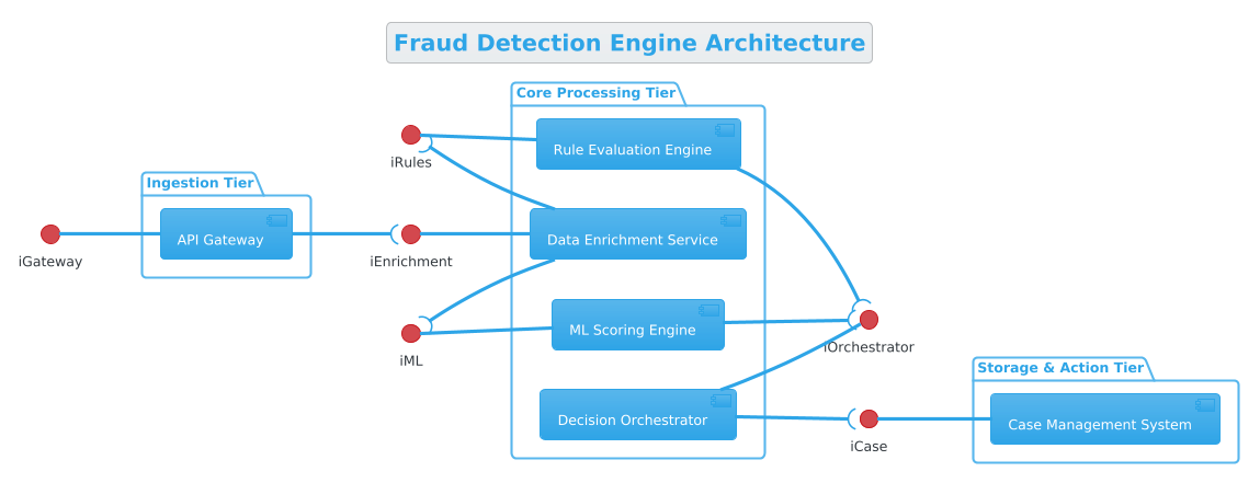
@startuml
!theme cerulean


title Fraud Detection Engine Architecture
/'
This component diagram illustrates the architectural layout of a real-time Fraud Detection Engine. It models the structured interactions between data ingestion services, machine learning evaluation pipelines, rule-based scoring modules, and downstream case management systems to protect high-volume transaction flows from malicious activity.
'/

left to right direction

skinparam componentStyle uml2

package "Ingestion Tier" {
  [API Gateway] as Gateway
}

package "Core Processing Tier" {
  [Data Enrichment Service] as Enrichment
  [Rule Evaluation Engine] as RulesEngine
  [ML Scoring Engine] as MLEngine
  [Decision Orchestrator] as Orchestrator
}

package "Storage & Action Tier" {
  [Case Management System] as CaseManager
}

' Provided Interfaces (on the left)
iGateway -- Gateway
iEnrichment -- Enrichment
iRules -- RulesEngine
iML -- MLEngine
iOrchestrator -- Orchestrator

' Required Interfaces (on the right)
Gateway --( iEnrichment
Enrichment --( iRules
Enrichment --( iML
RulesEngine --( iOrchestrator
MLEngine --( iOrchestrator
Orchestrator --( iCase

[Case Management System] as CaseManager
iCase -- CaseManager

@endooooStep-by-Step Architectural Walkthrough
Phase 1: Canvas Configuration & Layout Directives
Before defining any components, we must set the stage for how the diagram renders. This includes the diagram title, the visual theme, and the direction of the flow.
We begin with the @startuml directive and include the VPasCode theme library. This ensures that the diagram renders with the correct color palette and styling definitions available in the web editor.
!include https://static.visual-paradigm.com/web/resources/plantuml-stdlib/themes/vp.puml
!theme cerulean
Next, we define the title and the context. The comment block is crucial for documentation; it appears in the diagram header but does not clutter the visual layout.
title Fraud Detection Engine Architecture
/'
This component diagram illustrates the architectural layout of a real-time Fraud Detection Engine...
'/
We also enforce a left to right direction. In financial architecture diagrams, reading left-to-right often aligns with the flow of transaction data from entry to action.
left to right directionPhase 2: Declaring Core Entities, Actors, and Boundaries
Now we define the logical boundaries of the system using package blocks. This groups related components together, making the diagram easier to scan.
For the Ingestion Tier, we define the entry point:
package "Ingestion Tier" {
  [API Gateway] as Gateway
}
For the Core Processing Tier, we list the services that process the data. Notice we assign aliases (e.g., as Gateway) to make referencing easier later.
package "Core Processing Tier" {
  [Data Enrichment Service] as Enrichment
  [Rule Evaluation Engine] as RulesEngine
  [ML Scoring Engine] as MLEngine
  [Decision Orchestrator] as Orchestrator
}
Finally, the Storage & Action Tier captures the downstream systems.
package "Storage & Action Tier" {
  [Case Management System] as CaseManager
}
Phase 3: Mapping Data Flows & Key Interactions
The heart of a component diagram is the interface definition. In PlantUML, interfaces act as the ports through which components communicate.
Provided Interfaces (Left Side): These represent the services a component exposes to the world. We draw the interface symbol on the left side of the component.
iGateway -- Gateway
iEnrichment -- Enrichment
iRules -- RulesEngine
Required Interfaces (Right Side): These represent the services a component needs from others. We use the --( syntax to draw the interface on the right side of the component.
Gateway --( iEnrichment
Enrichment --( iRules
Enrichment --( iML
This creates a clear visual contract: The Gateway provides its interface, but requires the Enrichment service to function.
Phase 4: Grouping, Annotations & Visual Polish
To finalize the diagram, we ensure all connections are complete. The Orchestrator requires the Case Management system, so we define that link.
Orchestrator --( iCase
[Case Management System] as CaseManager
iCase -- CaseManager
We also apply the skinparam componentStyle uml2 directive to ensure the component boxes use the standard UML2 notation style, which is preferred for enterprise architecture.
Syntax & Keyword Deep Dive
Understanding the specific PlantUML keywords used in this Fraud Detection Engine diagram is essential for mastering the VPasCode editor.
package: Defines a logical grouping. It acts as a container for components, helping to separate concerns (e.g., Ingestion vs. Processing).[Component Name] as Alias: Creates a component shape and assigns a shorthand name. This is critical for connecting interfaces without repeating long names.--(Interface Connector): Connects a provided interface to a component. The interface symbol appears on the left.--((Required Interface Connector): Connects a component to a required interface. The interface symbol appears on the right, indicating a dependency./' ... '/(Comment Block): Used to add a multi-line description that renders in the diagram header without affecting the layout.!theme: Applies a specific color palette and style set to the entire diagram, ensuring consistency with your branding.
Best Practices & Pitfalls to Avoid
- Keep Interfaces Abstract: Do not list method signatures in component diagrams. Interfaces should represent high-level capabilities (e.g.,
iEnrichment), not specific function calls. - Consistent Naming: Always use aliases (e.g.,
as Gateway) when connecting components. This makes the connection lines cleaner and the code more readable. - Layered Architecture: Group components into packages that reflect your deployment or logical tiers (e.g., Ingestion, Core, Storage). This prevents a “spaghetti diagram” where everything is connected randomly.
- Directionality: Explicitly set
left to right directionat the start. Relying on defaults can lead to unpredictable layouts when you add new components later.
Try It Yourself with VPasCode
Start Building PlantUML Diagrams Faster with VPasCode
Instantly render, customize, and export your Fraud Detection Engine architecture online in VPasCode without installing any tools.