


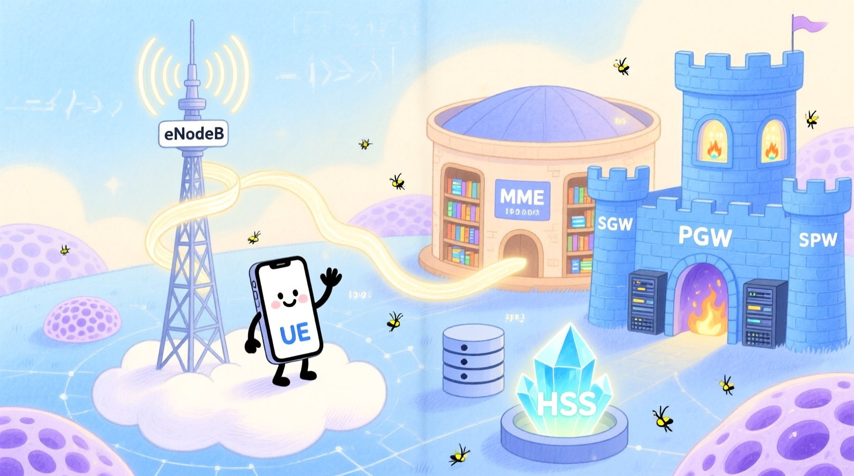
 This tutorial guides you through constructing a comprehensive sequence diagram for a Mobile Data Session Establishment scenario. We will break down the architecture of the PGW/SGW system, explore the specific PlantUML syntax required for combined fragments and participant definitions, and ensure your documentation remains synchronized with your architectural logic.
Understanding the Model: Purpose, Scope & Problem Framing
Before diving into the syntax, it is essential to understand the abstraction level of this diagram. A sequence diagram is the ideal choice for modeling the dynamic behavior of a system over time. Unlike class diagrams which focus on structure, this notation captures the temporal ordering of messages between actors and components.Diagram Abstraction & Representation
In this specific model, the vertical axis represents time progressing downwards, while the horizontal axis represents the different logical participants in the LTE network. The vertical lines extending from each participant are called lifelines, indicating their existence during the session. The horizontal arrows represent the messages exchanged, such as theAttach Request or Create Session Request, which drive the state changes within the network elements.
Target Domain Scope & Scenario
The scope of this diagram is strictly limited to the Initial Attachment and Bearer Setup phase of an LTE network. It covers the journey from the UE sending an RRC Connection Request to the final establishment of an IP Data Flow. Crucially, it also models conditional logic, such as the difference between an initial attachment and a handover scenario, or the optional discovery of the P-CSCF for VoLTE services.Key Takeaways & Educational Insights
By building this diagram in VPasCode, you will gain clarity on:- The precise sequence of authentication and location updates between MME and HSS.
- How session contexts are propagated from the MME to the SGW and PGW.
- How to visualize alternative paths using combined fragments like
altandelsewithout cluttering the main flow.
Complete Diagram & Full Source Code
Below is the finalized blueprint for the Mobile Data Session Establishment. This diagram encapsulates the full lifecycle of a data session, including error handling and optional features. You can copy this code directly into the VPasCode editor to see the live rendering.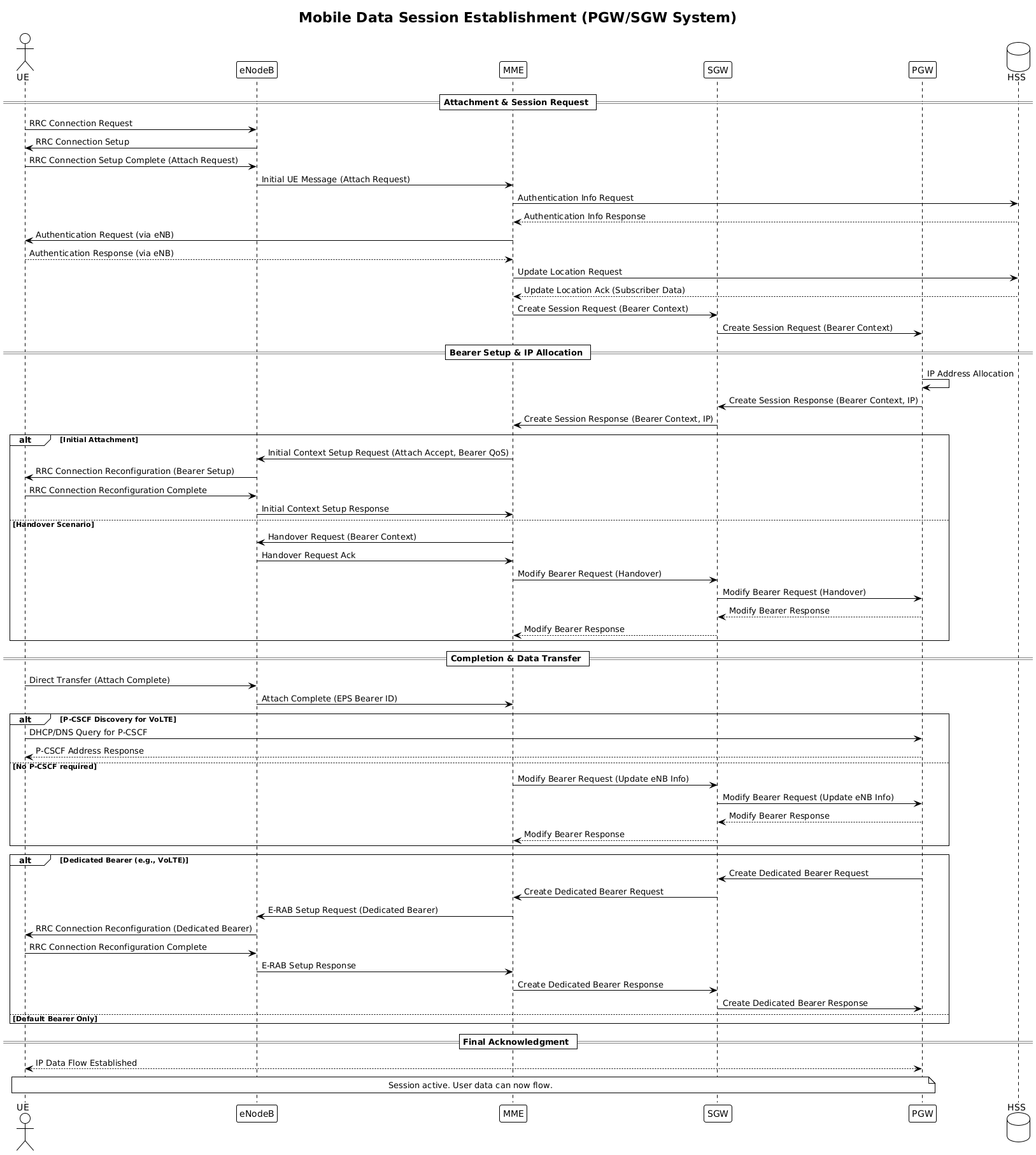
Plantuml
Edit Plantuml in VPasCode
@startuml
!theme plain
title Mobile Data Session Establishment (PGW/SGW System)

/'
This sequence diagram illustrates the establishment of a mobile data session
within an LTE/EPC network, focusing on the interaction between the UE, eNodeB,
MME, Serving Gateway (SGW), and Packet Data Network Gateway (PGW).

The flow covers the default bearer setup, including optional steps such as
P-CSCF discovery and dedicated bearer establishment for VoLTE.
Alternative paths are represented using combined fragments (alt/else)
to handle scenarios like initial attachment vs. handover, and
successful vs. failed bearer creation.
'/

actor UE
participant "eNodeB" as eNB
participant "MME" as MME
participant "SGW" as SGW
participant "PGW" as PGW
database "HSS" as HSS

== Attachment & Session Request ==

UE -> eNB: RRC Connection Request
eNB -> UE: RRC Connection Setup
UE -> eNB: RRC Connection Setup Complete (Attach Request)
eNB -> MME: Initial UE Message (Attach Request)

MME -> HSS: Authentication Info Request
HSS --> MME: Authentication Info Response
MME -> UE: Authentication Request (via eNB)
UE --> MME: Authentication Response (via eNB)
MME -> HSS: Update Location Request
HSS --> MME: Update Location Ack (Subscriber Data)

MME -> SGW: Create Session Request (Bearer Context)
SGW -> PGW: Create Session Request (Bearer Context)

== Bearer Setup & IP Allocation ==

PGW -> PGW: IP Address Allocation
PGW -> SGW: Create Session Response (Bearer Context, IP)
SGW -> MME: Create Session Response (Bearer Context, IP)

alt Initial Attachment
    MME -> eNB: Initial Context Setup Request (Attach Accept, Bearer QoS)
    eNB -> UE: RRC Connection Reconfiguration (Bearer Setup)
    UE -> eNB: RRC Connection Reconfiguration Complete
    eNB -> MME: Initial Context Setup Response
else Handover Scenario
    MME -> eNB: Handover Request (Bearer Context)
    eNB -> MME: Handover Request Ack
    MME -> SGW: Modify Bearer Request (Handover)
    SGW -> PGW: Modify Bearer Request (Handover)
    PGW --> SGW: Modify Bearer Response
    SGW --> MME: Modify Bearer Response
end

== Completion & Data Transfer ==

UE -> eNB: Direct Transfer (Attach Complete)
eNB -> MME: Attach Complete (EPS Bearer ID)

alt P-CSCF Discovery for VoLTE
    UE -> PGW: DHCP/DNS Query for P-CSCF
    PGW --> UE: P-CSCF Address Response
else No P-CSCF required
    MME -> SGW: Modify Bearer Request (Update eNB Info)
    SGW -> PGW: Modify Bearer Request (Update eNB Info)
    PGW --> SGW: Modify Bearer Response
    SGW --> MME: Modify Bearer Response
end

alt Dedicated Bearer (e.g., VoLTE)
    PGW -> SGW: Create Dedicated Bearer Request
    SGW -> MME: Create Dedicated Bearer Request
    MME -> eNB: E-RAB Setup Request (Dedicated Bearer)
    eNB -> UE: RRC Connection Reconfiguration (Dedicated Bearer)
    UE -> eNB: RRC Connection Reconfiguration Complete
    eNB -> MME: E-RAB Setup Response
    MME -> SGW: Create Dedicated Bearer Response
    SGW -> PGW: Create Dedicated Bearer Response
else Default Bearer Only
    note right: No dedicated bearer established
end

== Final Acknowledgment ==

UE <--> PGW: IP Data Flow Established
note over PGW, UE: Session active. User data can now flow.

@endumlStep-by-Step Architectural Walkthrough
Constructing this diagram requires a structured approach to ensure readability and accuracy. We will break the process into four logical phases.Phase 1: Canvas Configuration & Layout Directives
Every PlantUML diagram begins with configuration directives that set the global style. We start with@startuml to open the block. The !theme plain directive ensures a clean, minimalist look suitable for technical documentation. We define a title for the diagram and use a comment block wrapped in /' and '/ to provide context. This comment block is invisible in the rendered output but invaluable for maintainers reading the source code.
@startuml
!theme plain
title Mobile Data Session Establishment (PGW/SGW System)
/'
This sequence diagram illustrates...
'/
Phase 2: Declaring Core Entities, Actors, and Boundaries
Next, we define the participants. In telecommunications modeling, distinguishing between the Actor (the user device) and the System Components is vital. We declare the UE as an actor. Network elements like the eNodeB and MME are declared asparticipant elements. For the HSS (Home Subscriber Server), which is a database of subscriber records, we explicitly use the database keyword to visually distinguish it from standard participants.
actor UE
participant "eNodeB" as eNB
participant "MME" as MME
database "HSS" as HSS
Phase 3: Mapping Data Flows & Key Interactions
This is the core of the sequence diagram. We use horizontal arrows to show message flow. A solid arrow with a closed head (->) indicates a synchronous message, while a dashed arrow with an open head (-->) indicates a return message. We group messages into sections using == Section Title == to break the diagram into logical phases like Attachment & Session Request.
MME -> HSS: Authentication Info Request
HSS --> MME: Authentication Info Response
Phase 4: Grouping, Annotations & Visual Polish
To handle complex logic, we use Combined Fragments. Thealt block allows us to show alternative flows, such as an Initial Attachment versus a Handover Scenario. We close these blocks with end. We also add note annotations to explain specific states, such as when a dedicated bearer is not established. Finally, we use note over to place a note spanning multiple lifelines at the end of the session.
alt Initial Attachment
    ... messages ...
else Handover Scenario
    ... messages ...
end
Syntax & Keyword Deep Dive
Understanding the specific PlantUML keywords used in this diagram is crucial for extending the model in the future. Here is a breakdown of the critical syntax elements:actor: Defines a human or external system interacting with the model (e.g., the UE).participant: Represents an internal system component or service (e.g., MME, SGW).database: Renders a specific icon for data storage systems like the HSS.->and-->: Control message direction.->is the request,-->is the response.alt/else/end: These keywords create the logic gates.altstarts the alternative block,elsedefines the fallback condition, andendcloses the logic block.note: Used to add explanatory text.note rightplaces it to the right of a lifeline, whilenote overspans across multiple lifelines.
Best Practices & Pitfalls to Avoid
To maintain high-quality documentation using VPasCode, follow these modeling guidelines:- Modularize Complex Flows: If a sequence becomes too long, break it down into multiple diagrams (e.g., one for Authentication, one for Bearer Setup). This diagram balances both, but be wary of clutter.
- Consistent Naming: Use the
askeyword to assign short aliases (likeas eNB) to long participant names. This keeps the diagram clean while maintaining clarity in the code. - Logical Grouping: Always use
== Section ==headers to separate distinct phases of the protocol flow. This helps readers quickly locate theAuthenticationphase versus theData Transferphase. - Clear Conditional Logic: When using
altblocks, ensure the conditions are mutually exclusive and clearly labeled. Avoid nesting too manyaltblocks inside one another, as this reduces readability.
Start Building Sequence Diagrams Faster with VPasCode
Visualize complex LTE signaling flows instantly in your browser with VPasCode, the free PlantUML editor for telecom architects.