


In the rapidly evolving landscape of educational technology, the architecture of a Learning Management System (LMS) must be robust, modular, and clearly defined to support diverse user needs ranging from students and instructors to administrators. As systems scale, visualizing the structural boundaries and interaction points between different software modules becomes critical for maintaining system integrity and facilitating future development. A component diagram serves as the blueprint for these structural relationships, allowing architects to map out how services communicate without getting bogged down in implementation details.
Diagramming-as-code bridges the gap between static documentation and living architecture, enabling teams to define these structures using text that can be versioned, reviewed, and rendered instantly. By leveraging PlantUML within the VPasCode environment, developers can prototype complex educational platforms with zero local setup, ensuring that the visual model evolves alongside the codebase. This approach fosters clarity, reduces ambiguity in system design, and accelerates the onboarding process for new team members.

Understanding the Model: Purpose, Scope & Problem Framing
A component diagram is a specialized type of UML diagram that focuses on the physical or logical components of a system and their relationships. Unlike class diagrams that detail internal logic, component diagrams abstract the system into deployable units, emphasizing interfaces and dependencies. In the context of an LMS, this diagram type is essential for defining the separation of concerns between the user interface, business logic, and data management layers.
The scope of this model covers the architectural boundaries of the LMS, grouping components into three distinct packages: the Presentation Layer (user-facing portals), the Core Business Layer (educational services), and the Data & Integration Layer (backend services). This structure highlights the modularity of the system, ensuring that changes in one layer, such as updating the mobile app, do not inadvertently disrupt the core assessment logic.
Key takeaways from this model include a clear understanding of provided and required interfaces. You will learn how to define dependencies using ball-and-socket notation, ensuring that components declare exactly what they need and what they offer. This abstraction is vital for maintaining a decoupled architecture where services can be replaced or upgraded independently.
Complete Diagram & Full Source Code
Before diving into the syntax, visualize the end goal. The following diagram illustrates the Learning Management System architecture with clear directional flows and layered packaging.
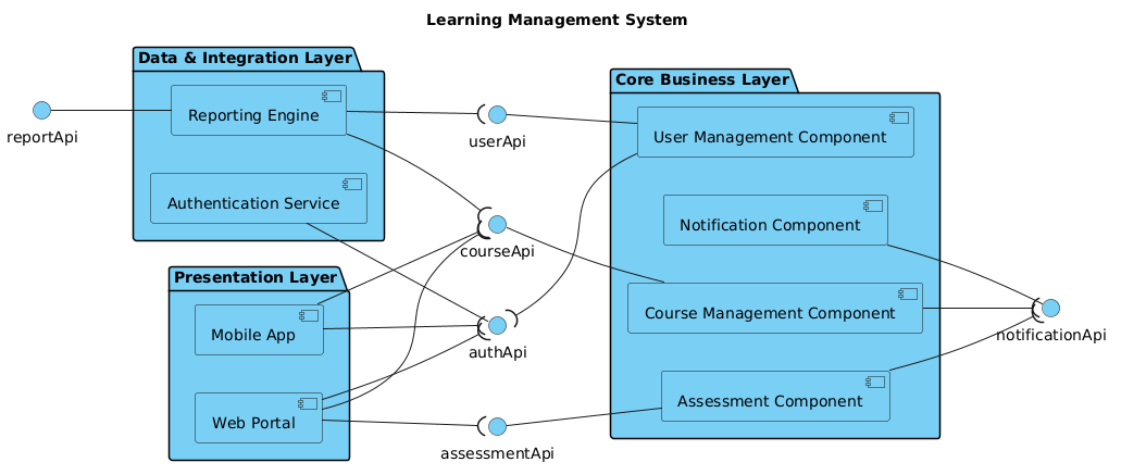
Below is the complete source code required to render this diagram in VPasCode. Copy this block directly into the editor to see the live rendering.
@startuml
!include https://static.visual-paradigm.com/web/resources/plantuml-stdlib/themes/vp.puml

title Learning Management System

/'
This component diagram outlines the architectural structure of a Learning Management System (LMS), illustrating the modular boundaries and integration points between user-facing portals, core educational services, and administrative subsystems.
'/

left to right direction

skinparam componentStyle uml2

package "Presentation Layer" {
    [Web Portal] as WebPortal
    [Mobile App] as MobileApp
}

package "Core Business Layer" {
    [User Management Component] as UserMgmt
    [Course Management Component] as CourseMgmt
    [Assessment Component] as Assessment
    [Notification Component] as Notification
}

package "Data & Integration Layer" {
    [Authentication Service] as AuthService
    [Reporting Engine] as Reporting
}

' Provided Interfaces (interface -- component)
authApi -- AuthService
userApi -- UserMgmt
courseApi -- CourseMgmt
assessmentApi -- Assessment
notificationApi -- Notification
reportApi -- Reporting

' Required Interfaces (component --( interface)
WebPortal --( authApi
WebPortal --( courseApi
WebPortal --( assessmentApi
MobileApp --( authApi
MobileApp --( courseApi

UserMgmt --( authApi
CourseMgmt --( notificationApi
Assessment --( notificationApi
Reporting --( userApi
Reporting --( courseApi

@endumlStep-by-Step Architectural Walkthrough
Constructing this diagram in VPasCode involves four logical phases. We will break down the code structure to understand how each part contributes to the final architectural view.
Phase 1: Canvas Configuration & Layout Directives
Every PlantUML diagram begins with setup directives that define the rendering engine and visual theme. We start by including the Visual Paradigm standard library theme to ensure consistent styling. Next, we set the title and add a comment block to document the diagram’s context. Finally, we configure the layout direction to flow from left to right, which is often more intuitive for reading layered architectures.
!include https://static.visual-paradigm.com/web/resources/plantuml-stdlib/themes/vp.puml

title Learning Management System

/'
This component diagram outlines the architectural structure of a Learning Management System (LMS)...
'/

left to right direction

skinparam componentStyle uml2
Phase 2: Declaring Core Entities, Actors, and Boundaries
The core of the model lies in defining the components and grouping them into packages. Packages act as containers to organize related components logically. In this LMS example, we define three main packages: Presentation, Core Business, and Data & Integration. Inside each package, we declare components using the square bracket syntax `[Component Name]` and assign them an alias for referencing later.
package "Presentation Layer" {
    [Web Portal] as WebPortal
    [Mobile App] as MobileApp
}

package "Core Business Layer" {
    [User Management Component] as UserMgmt
    [Course Management Component] as CourseMgmt
    [Assessment Component] as Assessment
    [Notification Component] as Notification
}
Phase 3: Mapping Data Flows & Key Interactions
Once the components are placed, we must define how they interact using interfaces. PlantUML uses specific arrow syntax to distinguish between provided and required interfaces. A provided interface is where a component offers functionality (interface on the left, component on the right), while a required interface is where a component needs functionality (component on the left, interface on the right).
' Provided Interfaces
authApi -- AuthService

' Required Interfaces
WebPortal --( authApi
MobileApp --( courseApi
Phase 4: Grouping, Annotations & Visual Polish
The final phase ensures all dependencies are mapped correctly. We connect the Presentation Layer components to the Core Business Layer via the required interface syntax. Notice how the `WebPortal` requires `authApi` and `courseApi`, indicating it depends on those services to function. This visualizes the contract between the UI and the backend logic without exposing internal implementation details.
Syntax & Keyword Deep Dive
Understanding the specific PlantUML keywords used in this LMS diagram is crucial for mastering component modeling. Below is a breakdown of the essential syntax elements.
package: Defines a container for grouping related components. This helps in managing visual complexity and represents architectural layers.[Component Name]: The syntax for declaring a standard component shape. The text inside brackets is the label displayed on the diagram.as Alias: Assigns a shorthand identifier to a component, allowing you to reference it in relationship lines without repeating the full name.--(Provided Interface): Connects an interface to a component where the component provides the functionality. The interface is always on the left side of the arrow.--((Required Interface): Connects a component to an interface where the component requires the functionality. The interface is always on the right side of the arrow./' ... '/: The syntax for multi-line comments. This is used to add context or documentation directly within the code file.
Best Practices & Pitfalls to Avoid
To ensure your component diagrams remain maintainable and clear, adhere to these modeling best practices:
- Keep Interfaces Explicit: Always define interfaces explicitly rather than connecting components directly. This enforces a contract-based architecture and reduces coupling.
- Consistent Naming Conventions: Use clear, descriptive names for both components and interfaces (e.g.,
authApiinstead ofapi1) to make the diagram self-documenting. - Limit Diagram Scope: Do not try to model every single method or attribute. Focus on high-level boundaries and service interactions to keep the diagram readable.
- Use Layers for Complexity: When dealing with large systems like an LMS, group components into packages (e.g., Presentation, Business, Data) to visually separate concerns.
Start Building LMS Component Diagrams Faster with VPasCode
Test, preview, and customize your Learning Management System architecture online in VPasCode without installing any tools.