


In the rapidly evolving telecommunications landscape, the ability to port phone numbers between carriers is a critical service that drives customer retention and market competition. For software architects and system designers, accurately modeling this workflow is essential to ensure seamless inter-carrier communication and data integrity. The Number Porting Process involves multiple entities—Donor Carriers, Recipient Carriers, Interconnection Gateways, and central Number Portability Databases—each performing distinct roles in a synchronized sequence.

Traditional flowcharting tools often struggle to represent the complexity of these multi-party interactions, particularly when dealing with conditional logic (e.g., validating subscriber eligibility) and parallel processing (e.g., notifying multiple systems simultaneously). This is where diagram-as-code shines. By using PlantUML within VPasCode, architects can define these intricate workflows in text, ensuring version stability, rapid iteration, and precise visual representation without the friction of drag-and-drop interfaces.
This tutorial demonstrates how to construct a professional activity diagram that maps the lifecycle of a porting request, from initial validation to final activation, leveraging VPasCode’s browser-based rendering engine to instantly visualize and refine your architectural models.
Understanding the Model: Purpose, Scope & Problem Framing
Diagram Abstraction & Representation
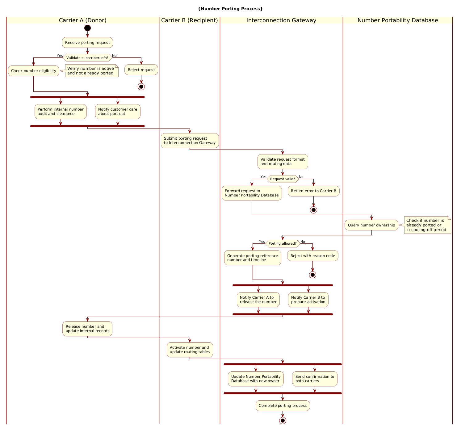
An Activity Diagram in PlantUML is the ideal notation for modeling the dynamic behavior of a system. Unlike static structure diagrams, activity diagrams focus on the flow of control and data. In this specific telecommunications scenario, we utilize swimlanes to visually segregate responsibilities between different organizational boundaries (Carrier A, Carrier B, Gateway, Database). This abstraction allows stakeholders to immediately identify bottlenecks, decision points, and parallel execution paths.
Target Domain Scope & Scenario
The scope of this model covers the end-to-end technical process of a Mobile Number Portability (MNP) transaction. It intentionally excludes the internal CRM workflows of the carriers themselves, focusing strictly on the inter-carrier signaling required to transfer ownership. The scenario addresses:
- Validation: Ensuring the number is eligible for porting before resources are committed.
- Interconnection: The role of the Gateway as the central routing hub.
- Synchronization: Managing the parallel notifications required to both release (Donor) and prepare (Recipient) the number.
Key Takeaways & Educational Insights
By building this diagram, you will gain clarity on how to model complex distributed systems. You will learn how to use forks to represent parallel system calls, how to apply notes for critical business rules (like cooling-off periods), and how to manage conditional branching to handle error states gracefully.
Complete Diagram & Full Source Code
Below is the complete, finalized blueprint for the Number Porting Process. This diagram utilizes the Rose theme for a professional aesthetic and structures the workflow across four distinct swimlanes to clarify ownership of each action.
@startuml
!include https://static.visual-paradigm.com/web/resources/plantuml-stdlib/themes/rose.puml

title {Number Porting Process}

|Carrier A (Donor)|
start
:Receive porting request;

|Carrier A (Donor)|
if (Validate subscriber info?) then (Yes)
  :Check number eligibility;
  note right
    Verify number is active
    and not already ported
  end note
else (No)
  :Reject request;
  stop
endif

|Carrier A (Donor)|
fork
  :Perform internal number
  audit and clearance;
fork again
  :Notify customer care
  about port-out;
end fork

|Carrier B (Recipient)|
:Submit porting request
to Interconnection Gateway;

|Interconnection Gateway|
:Validate request format
and routing data;

|Interconnection Gateway|
if (Request valid?) then (Yes)
  :Forward request to
  Number Portability Database;
else (No)
  :Return error to Carrier B;
  stop
endif

|Number Portability Database|
:Query number ownership;
note right
  Check if number is
  already ported or
  in cooling-off period
end note

|Interconnection Gateway|
if (Porting allowed?) then (Yes)
  :Generate porting reference
  number and timeline;
else (No)
  :Reject with reason code;
  stop
endif

|Interconnection Gateway|
fork
  :Notify Carrier A to
  release the number;
fork again
  :Notify Carrier B to
  prepare activation;
end fork

|Carrier A (Donor)|
:Release number and
update internal records;

|Carrier B (Recipient)|
:Activate number and
update routing tables;

|Interconnection Gateway|
fork
  :Update Number Portability
  Database with new owner;
fork again
  :Send confirmation to
  both carriers;
end fork

|Interconnection Gateway|
:Complete porting process;

stop
@endumlStep-by-Step Architectural Walkthrough
Phase 1: Canvas Configuration & Layout Directives
Before defining the workflow logic, we establish the visual theme and the title of the diagram. This ensures consistency and professional presentation immediately upon rendering.
First, we include the Rose theme library. This provides a standardized color palette and styling for nodes and connectors. Next, we define the title using the title directive.
!include https://static.visual-paradigm.com/web/resources/plantuml-stdlib/themes/rose.puml

title {Number Porting Process}
Phase 2: Declaring Core Entities, Actors, and Boundaries
The backbone of this diagram is the swimlane structure. Swimlanes allow us to group activities by the system or entity responsible for them. In PlantUML, swimlanes are declared using the pipe character | followed by the entity name.
We define the primary actors: Carrier A (Donor), Carrier B (Recipient), the Interconnection Gateway, and the Number Portability Database.
|Carrier A (Donor)|
|Carrier B (Recipient)|
|Interconnection Gateway|
|Number Portability Database|
Phase 3: Mapping Data Flows & Key Interactions
With the lanes established, we map the flow of the porting request. We start with the start node and end with stop. The core logic involves conditional checks and parallel processing.
For the initial validation, we use the if-endif syntax to check subscriber eligibility. If the check fails, the process terminates early via the stop node, preventing unnecessary downstream processing.
if (Validate subscriber info?) then (Yes)
  :Check number eligibility;
else (No)
  :Reject request;
  stop
endif
Phase 4: Grouping, Annotations & Visual Polish
To add clarity, we use Forks to represent parallel actions. For instance, after validation, the Gateway must simultaneously notify the Donor to release resources and the Recipient to prepare activation. This is achieved using the fork and fork again keywords.
Additionally, we attach Notes to specific nodes to document business rules that are critical for implementation but clutter the flowchart visually.
note right
  Check if number is
  already ported or
  in cooling-off period
end note
Syntax & Keyword Deep Dive
Understanding the specific PlantUML syntax is crucial for mastering diagram-as-code. Here is a breakdown of the key constructs used in this telecommunications model:
|Lane Name|: Defines a swimlane. All subsequent actions are visually grouped under this entity until a new lane is declared.start/stop: Marks the entry and exit points of the activity flow. Thestopnode is critical for modeling error termination paths.if (Condition?) then (Yes): Creates a decision diamond. The text inside the parentheses defines the label for the “Yes” branch.else (No): Defines the alternative path for the decision node.fork/fork again/end fork: Creates parallel branches. Actions betweenforkandfork againexecute concurrently with actions betweenfork againandend fork.note right/note left: Attaches a text annotation to the preceding element, useful for adding constraints or business rules without altering the flow path.
Best Practices & Pitfalls to Avoid
To maintain high-quality diagrams that serve as effective documentation, adhere to these modeling guidelines:
- Maintain Swimlane Clarity: Ensure every action is assigned to the correct entity. Avoid placing actions in the wrong lane, as this misrepresents system responsibility.
- Limit Parallelism: While
forkis powerful, avoid nesting too many levels of parallel execution. Keep the diagram readable by limiting forks to 2-3 distinct paths per intersection. - Use Descriptive Labels: Instead of generic labels like “Process,” use specific verbs like “Validate subscriber info” or “Update routing tables” to make the diagram self-explanatory.
- Handle Error Paths Explicitly: Never assume success. Always model the
elsebranch for critical validation steps to show how the system handles failures gracefully.
Start Building PlantUML Activity Diagrams Faster with VPasCode
Instantly preview and customize your Carrier Interconnection Gateway workflows online in VPasCode without installing any tools.