


In the fast-paced retail industry, customer retention is often driven by sophisticated loyalty programs. These programs rely on complex data relationships: tracking a customer’s journey from sign-up to tier advancement, calculating point accruals from various transactions, and managing the redemption of rewards against available balances. Without a clear, unified data model, these systems can quickly become fragmented, leading to inaccurate point calculations, tier status errors, and a poor customer experience.
Designing an Entity Relationship Diagram (ERD) for such a system requires more than just listing tables; it demands a deep understanding of cardinality, foreign key constraints, and the temporal nature of loyalty status. By using diagram-as-code with PlantUML, architects can define these relationships with precision, ensuring that every transaction, redemption, and status update is logically connected. This approach not only serves as a blueprint for database development but also acts as living documentation that evolves alongside the business logic.
Understanding the Model: Purpose, Scope & Problem Framing
This tutorial focuses on constructing a comprehensive ERD for a Customer Loyalty Program. The primary objective is to model the data structures required to track membership tiers, accumulate points through transactions, and process reward redemptions while maintaining accurate balance histories.
Diagram Abstraction & Representation
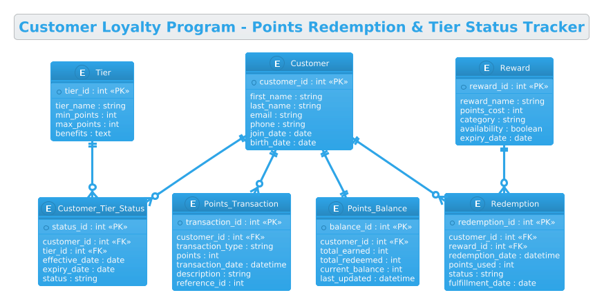
An Entity Relationship Diagram is the standard visual language for defining database schemas. In this context, each Entity represents a critical business object: Customer (the member), Tier (the membership level), Points_Transaction (the history of earning), and Redemption (the history of spending). The relationships (lines) between these entities define the rules of the system, such as ensuring a customer can only have one active tier status at a time or that a redemption is always linked to a specific reward.
Target Domain Scope & Scenario
The scope of this model covers the entire lifecycle of a loyalty member within a retail environment. It intentionally excludes external payment gateway integrations or marketing campaign management, focusing strictly on the core data integrity required for the loyalty engine. Key scenarios modeled include:
- Tier Management: Tracking a customer’s current tier and the history of status changes based on point thresholds.
- Point Accrual: Recording every transaction that adds points to a customer’s account.
- Redemption Logic: Linking a customer to a specific reward and deducting the corresponding points.
- Balance Tracking: Maintaining a real-time snapshot of total earned, total redeemed, and current available points.
Key Takeaways & Educational Insights
By building this diagram, you will learn how to model many-to-many relationships (like customers redeeming multiple rewards) using junction tables, how to handle temporal data (effective/expiry dates) for status tracking, and how to separate transactional history from current state snapshots. This ensures a normalized, scalable database design that can handle high-volume retail transactions.
Complete Diagram & Full Source Code
Below is the final rendered diagram representing the Customer Loyalty Program. It features the Cerulean theme for a clean, professional look, clearly distinguishing between primary keys, foreign keys, and the logical flow of data.
@startuml
!theme cerulean
title Customer Loyalty Program - Points Redemption & Tier Status Tracker

/'
This ERD models the core data structure for a customer loyalty program.
It captures customers, their membership tiers, point-earning transactions,
point redemptions for rewards, and the current point balances and tier
statuses needed to manage loyalty benefits. The diagram connects customer
accounts to tier levels and tracks both earned and spent points over time.
'/

entity "Customer" as customer {
  * customer_id : int <<PK>>
  --
  first_name : string
  last_name : string
  email : string
  phone : string
  join_date : date
  birth_date : date
}

entity "Tier" as tier {
  * tier_id : int <<PK>>
  --
  tier_name : string
  min_points : int
  max_points : int
  benefits : text
}

entity "Customer_Tier_Status" as customer_tier_status {
  * status_id : int <<PK>>
  --
  customer_id : int <<FK>>
  tier_id : int <<FK>>
  effective_date : date
  expiry_date : date
  status : string
}

entity "Points_Transaction" as points_transaction {
  * transaction_id : int <<PK>>
  --
  customer_id : int <<FK>>
  transaction_type : string
  points : int
  transaction_date : datetime
  description : string
  reference_id : int
}

entity "Reward" as reward {
  * reward_id : int <<PK>>
  --
  reward_name : string
  points_cost : int
  category : string
  availability : boolean
  expiry_date : date
}

entity "Redemption" as redemption {
  * redemption_id : int <<PK>>
  --
  customer_id : int <<FK>>
  reward_id : int <<FK>>
  redemption_date : datetime
  points_used : int
  status : string
  fulfillment_date : date
}

entity "Points_Balance" as points_balance {
  * balance_id : int <<PK>>
  --
  customer_id : int <<FK>>
  total_earned : int
  total_redeemed : int
  current_balance : int
  last_updated : datetime
}

customer ||--o{ customer_tier_status
tier ||--o{ customer_tier_status
customer ||--o{ points_transaction
customer ||--o{ redemption
reward ||--o{ redemption
customer ||--|| points_balance

@endumlStep-by-Step Architectural Walkthrough
Building a robust ERD requires a methodical approach. We will break down the construction of this loyalty program schema into four distinct phases, moving from global configuration to specific entity definitions and finally to relationship mapping.
Phase 1: Canvas Configuration & Layout Directives
Every PlantUML diagram begins with configuration directives that set the global behavior and aesthetics. In this model, we start by declaring the theme to ensure visual consistency.
First, we define the entry point with @startuml. Immediately following, we apply the !theme cerulean directive. This applies a pre-defined color palette (blues, whites, and grays) that is particularly suitable for enterprise and financial data models, providing a clean and professional appearance without manual styling.
@startuml
!theme cerulean
title Customer Loyalty Program - Points Redemption & Tier Status Tracker
Next, we include a comment block using the /' ... '/ syntax. This is crucial for documentation; it allows us to describe the diagram’s intent and scope directly within the code, serving as a README for anyone reviewing the schema later.
Phase 2: Declaring Core Entities, Actors, and Boundaries
With the canvas ready, we define the core entities. In PlantUML ERD syntax, we use the entity keyword. Each entity is named (e.g., "Customer") and assigned an alias (e.g., as customer) to be used in relationship definitions.
Inside each entity block, we define attributes. We use the asterisk * to denote Primary Keys (PK) and the double chevrons < to denote Foreign Keys. For example, the Customer entity is the central actor:
entity "Customer" as customer {
  * customer_id : int <>
  --
  first_name : string
  last_name : string
  email : string
  ...
Notice the -- separator line. This is a stylistic choice in PlantUML that visually separates the primary key from the other attributes, improving readability. We also define the Tier entity to store membership levels and the Reward entity to store the catalog of items available for redemption.
Phase 3: Mapping Data Flows & Key Interactions
The power of an ERD lies in the relationships. We use the ||--o{ and ||--|| syntax to define cardinality. This phase connects the entities we defined in the previous step.
Consider the Points_Transaction entity. A single customer can have many transactions, but each transaction belongs to exactly one customer. This is a one-to-many relationship:
customer ||--o{ points_transactionHere, || represents the “one” side (Customer) and o{ represents the “many” (zero or more) side (Transactions). Similarly, the Redemption entity acts as a bridge between Customer and Reward, allowing a customer to redeem multiple rewards over time, and a reward to be redeemed by multiple customers.
Phase 4: Grouping, Annotations & Visual Polish
In this final phase, we ensure the diagram handles complex business rules. The Customer_Tier_Status entity is a classic example of a temporal bridge table. It links a customer to a tier but also includes effective_date and expiry_date. This allows the system to track historical tier changes, not just the current status.
We also define the Points_Balance entity. The relationship customer ||--|| points_balance uses || on both ends, indicating a strict one-to-one relationship. This implies that at any given moment, a customer has exactly one active balance record that aggregates their total earned and redeemed points.
Syntax & Keyword Deep Dive
To master PlantUML ERD modeling, you must understand the specific keywords and symbols used to define structure and relationships.
entity: The fundamental building block. It defines a table or class. Syntax:entity "Name" as alias { ... }.!!(Primary Key Marker): Placed before an attribute name (e.g.,* customer_id) to visually and semantically indicate it is the Primary Key.<(Foreign Key Stereotype): Used to explicitly mark attributes that reference a Primary Key in another entity. This helps in generating accurate SQL scripts.> ||--o{(Cardinality): Represents a One-to-Many relationship.||is the mandatory one side,o{is the optional many side.||--||(Cardinality): Represents a One-to-One relationship. Both sides are mandatory.!theme: A directive to apply a specific visual theme to the entire diagram, overriding default colors and fonts./' ... '/: A multi-line comment block used for documentation within the code.
Best Practices & Pitfalls to Avoid
When modeling complex retail systems like loyalty programs, adhering to best practices ensures your diagram remains maintainable and your database performs well.
- Normalize Your Data: Avoid storing redundant data like “current tier name” directly in the
Customertable. Instead, link to aTiertable or use aCustomer_Tier_Statustable. This prevents data inconsistencies if a tier’s name changes. - Use Descriptive Aliases: When defining entities, use short, meaningful aliases (e.g.,
as customer) for the relationship lines. This makes the code significantly easier to read than long entity names. - Separate History from State: As seen in this model, separate the
Points_Transaction(history) from thePoints_Balance(current state). This is a common pattern in financial systems to ensure auditability. - Consistent Naming Conventions: Stick to a consistent naming convention (e.g., camelCase for aliases, Title Case for entity names) to maintain professionalism and clarity.
Start Building Retail ERDs Faster with VPasCode
Instantly visualize your Customer Loyalty Program schema with zero setup, test your syntax live in the browser, and export your professional ERD for your team.