


In the rapidly evolving landscape of retail technology, clarity in requirements is paramount. Whether you are architecting a new online marketplace or refactoring an existing legacy platform, visualizing how users interact with the system is critical for aligning stakeholders and developers. A Use Case Diagram serves as the foundational blueprint for this understanding, mapping out the functional goals of the system against the roles that achieve them.

However, traditional diagramming tools often introduce friction through complex GUIs or require heavy installation. This is where VPasCode changes the workflow. As a free, web-based diagram-as-code editor, VPasCode allows software engineers and architects to write PlantUML code directly in the browser, rendering professional diagrams instantly. By treating diagrams as code, you ensure versioning-friendly documentation, rapid prototyping, and seamless integration into your technical writing without the overhead of local environment setup.
Understanding the Model: Purpose, Scope & Problem Framing
Diagram Abstraction & Representation
A Use Case Diagram is a behavioral model that describes the static, functional relationships between actors and use cases. In the context of an E-commerce Storefront, it abstracts the system into a “black box” where internal implementation details are hidden, focusing instead on what the system does and who interacts with it. Actors represent external entities (users or systems) that initiate actions, while use cases represent specific functional goals, such as “Browse Products” or “Place Order”.
Target Domain Scope & Scenario
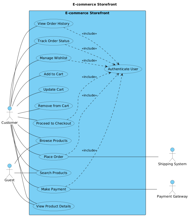
This tutorial models the core customer-facing functionality of a retail platform. The scope intentionally excludes back-office administration (like inventory management or staff login) to focus on the primary revenue-generating workflow. We define the system boundary as the “E-commerce Storefront” rectangle. Primary actors (Customer, Guest) reside on the left, initiating the flow, while secondary actors (Payment Gateway, Shipping System) reside on the right, supporting backend processes.
Key Takeaways & Educational Insights
- Boundary Definition: Learn how to encapsulate system functionality within a rectangle to clearly distinguish internal logic from external interactions.
- Actor Roles: Understand the distinction between primary actors (who start the process) and secondary actors (who support the process).
- Relationships: Master the syntax for associations and includes to model mandatory dependencies between use cases.
Complete Diagram & Full Source Code
Before diving into the step-by-step construction, review the complete blueprint below. This represents the final state of the diagram, showcasing the clean structure and professional styling available via VPasCode.
@startuml
!include https://static.visual-paradigm.com/web/resources/plantuml-stdlib/themes/vp.puml

title E-commerce Storefront

/'
  This use case diagram models the core functionality of a typical e-commerce storefront system.
  It captures the interactions between customers (primary actors) and the system's key features,
  such as browsing products, managing a shopping cart, placing orders, and handling payments.
  Secondary actors represent external systems that support order fulfillment and payment processing.
  The diagram focuses on the customer-facing side of the platform, excluding back-office administration.
'/

left to right direction

actor "Customer" as customer
actor "Guest" as guest

rectangle "E-commerce Storefront" {
  usecase "Browse Products" as UC1
  usecase "Search Products" as UC2
  usecase "View Product Details" as UC3
  usecase "Add to Cart" as UC4
  usecase "Update Cart" as UC5
  usecase "Remove from Cart" as UC6
  usecase "Proceed to Checkout" as UC7
  usecase "Place Order" as UC8
  usecase "Make Payment" as UC9
  usecase "View Order History" as UC10
  usecase "Track Order Status" as UC11
  usecase "Manage Wishlist" as UC12
  usecase "Authenticate User" as UC13
}

actor "Payment Gateway" as paymentGateway
actor "Shipping System" as shippingSystem

customer -- UC1
customer -- UC2
customer -- UC3
customer -- UC4
customer -- UC5
customer -- UC6
customer -- UC7
customer -- UC8
customer -- UC9
customer -- UC10
customer -- UC11
customer -- UC12

guest -- UC1
guest -- UC2
guest -- UC3

UC8 --- shippingSystem
UC9 --- paymentGateway

' Included use case
UC7 ..> UC13 : <<include>>
UC8 ..> UC13 : <<include>>
UC9 ..> UC13 : <<include>>
UC10 ..> UC13 : <<include>>
UC11 ..> UC13 : <<include>>
UC12 ..> UC13 : <<include>>

@endumlStep-by-Step Architectural Walkthrough
Phase 1: Canvas Configuration & Layout Directives
Every PlantUML diagram begins with setup commands that define the theme and layout. In VPasCode, we leverage the Visual Paradigm standard library to ensure a consistent, professional aesthetic without manual CSS tweaking.
First, we include the theme library:
!include https://static.visual-paradigm.com/web/resources/plantuml-stdlib/themes/vp.pumlNext, we set the diagram title and the comment block. The comment block (starting with /) provides context for the diagram without rendering visually, which is excellent for documentation:
title E-commerce Storefront

/'
  This use case diagram models the core functionality...
'/
We also enforce a horizontal layout to accommodate the left-to-right flow of actors and use cases:
left to right directionPhase 2: Declaring Core Entities, Actors, and Boundaries
The heart of a Use Case Diagram is the system boundary. In PlantUML, we use the rectangle keyword to encapsulate use cases. This visually separates the system’s internal functions from the external world.
First, declare the primary actors. We assign aliases (e.g., as customer) to reference them later in relationships:
actor "Customer" as customer
actor "Guest" as guest
Inside the rectangle, we define the use cases. Each use case gets a unique alias and a label:
rectangle "E-commerce Storefront" {
  usecase "Browse Products" as UC1
  usecase "Place Order" as UC8
  usecase "Authenticate User" as UC13
}
Phase 3: Mapping Data Flows & Key Interactions
With the canvas and entities defined, we now map the relationships. Associations are drawn using the -- operator. In this diagram, we distinguish between primary and secondary interactions.
Connect primary actors to their respective use cases:
customer -- UC1
guest -- UC1
Connect secondary actors (external systems) to the use cases they support. Notice the use of --- to visually differentiate external dependencies:
UC8 --- shippingSystem
UC9 --- paymentGateway
Phase 4: Grouping, Annotations & Visual Polish
Finally, we handle the logical dependencies. In this scenario, actions like “Place Order” or “Make Payment” include the action of “Authenticate User.” This is represented by a dotted line with an arrow pointing to the included use case and a stereotype label.
UC8 ..> UC13 : <> This syntax indicates that UC13 is a mandatory part of UC8. In VPasCode, you can render this instantly to verify the flow direction and ensure the diagram matches the intended business logic.
Syntax & Keyword Deep Dive
To master PlantUML in VPasCode, understanding the specific keywords used in this model is essential. Below is a breakdown of the critical syntax elements.
actor: Declares an external entity interacting with the system. Syntax:actor "Name" as alias.rectangle: Defines the system boundary. Everything inside is considered part of the system.usecase: Defines a functional goal or service provided by the system. Syntax:usecase "Name" as alias.--: Represents an association (link) between an actor and a use case. No arrowhead is used by default in this style...>: Represents an include relationship. The arrow points to the use case being included.<<include>>: The stereotype label that explicitly defines the type of relationship on the arrow./…/: The comment block syntax used to add descriptive text that does not appear in the rendered diagram.
Best Practices & Pitfalls to Avoid
When modeling complex systems like e-commerce platforms, clarity is more important than completeness. Follow these guidelines to maintain high-quality diagrams:
- Keep Boundaries Tight: Do not include internal database tables or API endpoints in a Use Case Diagram. Stick to functional goals visible to the user.
- Use Meaningful Aliases: While
UC1works for small diagrams, use descriptive aliases likeplaceOrderin larger models to improve code readability. - Avoid Over-Connection: Ensure every line represents a meaningful interaction. If an actor connects to every use case, the diagram becomes cluttered and loses its architectural value.
- Separate Concerns: If your system has distinct user groups (e.g., Admin vs. Customer), consider splitting them into separate diagrams rather than one massive diagram.
Try It Yourself with VPasCode
Start Building Use Case Diagrams Faster with VPasCode
Design clear, professional e-commerce requirement models instantly in your browser with VPasCode’s free PlantUML editor—no installation required.