


In the high-stakes environment of financial technology, clarity is currency. A Retail Banking Core System is not merely a collection of software functions; it is a complex ecosystem where customer data, transaction integrity, and regulatory compliance intersect. For software architects and developers, visualizing this architecture is critical to ensure that the system remains modular, maintainable, and scalable.

Traditional drag-and-drop diagramming tools often lead to “diagram drift,” where visual representations become disconnected from the actual codebase. Diagram-as-code approaches, specifically using PlantUML, solve this by keeping the architecture documentation in sync with development logic. By defining components, interfaces, and dependencies through code, teams can version their architecture, automate testing, and generate consistent documentation.
In this masterclass, we will build a comprehensive Retail Banking Core System Component Diagram using VPasCode. We will explore how to structure architectural layers, define strict interface contracts using ball-and-socket notation, and organize the system into logical packages. This guide demonstrates how to leverage the VPasCode editor to prototype, refine, and document complex financial system architectures with zero setup.
Complete Diagram & Full Source Code
Before diving into the construction phases, here is the complete blueprint of the Retail Banking Core System. This diagram encapsulates four primary architectural domains: Customer Management, Account & Transaction Processing, Product & Pricing, and Integration & Reporting.
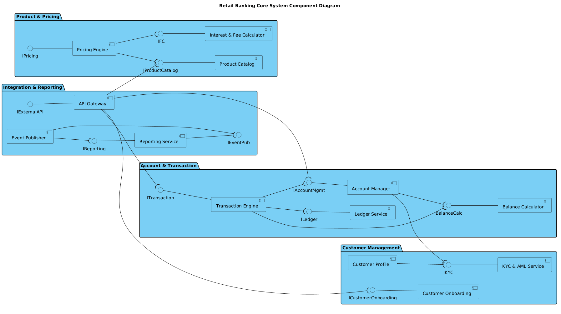
Below is the full PlantUML source code. You can copy this directly into the VPasCode editor to render the diagram instantly.
@startuml
!include https://static.visual-paradigm.com/web/resources/plantuml-stdlib/themes/vp.puml

title Retail Banking Core System Component Diagram

/'
This component diagram illustrates the high-level architecture of a Retail Banking Core System.
It captures the primary functional domains and their key software components, focusing on
the interfaces (provided and required) that enable modular integration. The system is
structured into distinct architectural layers: Customer Management, Account & Transaction
Processing, Product & Pricing, and Integration & Reporting. The diagram helps visualize
dependencies between components, highlighting how the system exposes services to external
channels and consumes internal services for data and processing. It serves as a blueprint
for system decomposition, interface design, and dependency management in a microservices
or modular monolith context.
'/

left to right direction

package "Customer Management" {
    component "Customer Onboarding" as CO
    component "KYC & AML Service" as KYC
    component "Customer Profile" as CP

    interface "ICustomerOnboarding" as ICO
    interface "IKYC" as IKY

    ICO -- CO
    IKY -- KYC

    CP --( IKY
}

package "Account & Transaction" {
    component "Account Manager" as AM
    component "Transaction Engine" as TE
    component "Ledger Service" as LS
    component "Balance Calculator" as BC

    interface "IAccountMgmt" as IAM
    interface "ITransaction" as ITX
    interface "ILedger" as ILED
    interface "IBalanceCalc" as IBAL

    IAM -- AM
    ITX -- TE
    ILED -- LS
    IBAL -- BC

    AM --( IKY
    TE --( IAM
    TE --( ILED
    TE --( IBAL
    AM --( IBAL
}

package "Product & Pricing" {
    component "Product Catalog" as PC
    component "Pricing Engine" as PE
    component "Interest & Fee Calculator" as IFC

    interface "IProductCatalog" as IPC
    interface "IPricing" as IPR
    interface "IIFC" as IIFC

    IPC -- PC
    IPR -- PE
    IIFC -- IFC

    PE --( IPC
    PE --( IIFC
}

package "Integration & Reporting" {
    component "API Gateway" as APIG
    component "Event Publisher" as EP
    component "Reporting Service" as RS

    interface "IExternalAPI" as IAPI
    interface "IEventPub" as IEVT
    interface "IReporting" as IREP

    IAPI -- APIG
    IEVT -- EP
    IREP -- RS

    APIG --( ICO
    APIG --( IAM
    APIG --( ITX
    APIG --( IPC
    EP --( IREP
    RS --( IEVT
}

@endumlStep-by-Step Architectural Walkthrough
Constructing a professional component diagram requires a logical flow. We will build this diagram in four distinct phases, moving from global configuration to specific component interactions.
Phase 1: Canvas Configuration & Layout Directives
Every PlantUML diagram begins with setup. We need to define the global theme, the diagram title, and the reading direction. In a banking system, clarity is paramount, so we use the left to right direction to align with standard Western reading patterns.
First, we include the VPasCode theme to ensure the diagram renders with professional styling consistent with Visual Paradigm standards. We also add a title directive and a comment block to document the context of the diagram.
@startuml
!include https://static.visual-paradigm.com/web/resources/plantuml-stdlib/themes/vp.puml

title Retail Banking Core System Component Diagram

/'
This component diagram illustrates the high-level architecture of a Retail Banking Core System.
It captures the primary functional domains and their key software components...
'/

left to right direction
Phase 2: Declaring Core Entities, Actors, and Boundaries
The heart of a component diagram lies in the package blocks. We group components logically to reflect business domains. Let’s start with the Customer Management package. This section handles the lifecycle of the customer, including onboarding and regulatory checks.
We define components using the component keyword and assign them unique aliases for referencing later. Crucially, we also define interfaces. In PlantUML, interfaces represent the services a component exposes (provided) or requires (consumed).
package "Customer Management" {
    component "Customer Onboarding" as CO
    component "KYC & AML Service" as KYC
    component "Customer Profile" as CP

    interface "ICustomerOnboarding" as ICO
    interface "IKYC" as IKY

    ICO -- CO
    IKY -- KYC

    CP --( IKY
}
Notice the relationship ICO -- CO. This indicates that the Customer Onboarding component provides the ICustomerOnboarding interface. This is a “ball-and-socket” joint where the component has the socket (accepts connections) and the interface is the ball (exposes the contract).
Phase 3: Mapping Data Flows & Key Interactions
The Account & Transaction package represents the most critical logic in a banking system. Here, we define the core processing engines. We must explicitly show how these components interact with the Customer Management layer.
For example, the Transaction Engine needs to verify KYC status before processing. We use the --( syntax to denote a Required Interface. The parenthesis indicates that the component on the left requires the service on the right.
package "Account & Transaction" {
    component "Transaction Engine" as TE
    component "Ledger Service" as LS

    interface "ITransaction" as ITX
    interface "ILedger" as ILED

    ITX -- TE
    ILED -- LS

    TE --( IKY
    TE --( ILED
}
Here, TE --( IKY means the Transaction Engine requires the IKYC interface. This visualizes the dependency clearly: without KYC, the Transaction Engine cannot function.
Phase 4: Grouping, Annotations & Visual Polish
The final layer is Integration & Reporting. This acts as the boundary between the core system and external channels (like mobile banking apps or third-party aggregators). The API Gateway is the primary entry point.
We group the external interfaces and connect the Gateway to the internal core services. This demonstrates how the core system exposes its capabilities (like IAccountMgmt or ITransaction) to the outside world while consuming internal reporting services.
package "Integration & Reporting" {
    component "API Gateway" as APIG

    interface "IExternalAPI" as IAPI

    IAPI -- APIG

    APIG --( ICO
    APIG --( IAM
    APIG --( ITX
}
By organizing the code this way, we ensure the generated diagram maintains a clean, hierarchical structure that mirrors the actual microservices or modular architecture of the banking platform.
Syntax & Keyword Deep Dive
To master PlantUML component diagrams, you must understand the specific syntax for defining relationships. Here is a breakdown of the key keywords used in this tutorial:
package: Defines a logical grouping or namespace for components. Essential for organizing complex systems into manageable domains like “Customer Management”.component: Represents a deployable unit of software. It is the standard building block for component diagrams.interface: Defines a contract of services. Interfaces allow components to communicate without knowing the internal implementation details of each other.--(Solid Line): Indicates a provided interface. The component on the right provides the service defined by the interface on the left.--((Line with Parenthesis): Indicates a required interface. The component on the left requires the service defined by the interface on the right. The parenthesis acts as the socket.title: Sets the main heading of the diagram, providing immediate context for the viewer./' ... '/: Defines a multi-line comment block. This is perfect for architectural context notes that don’t clutter the visual diagram but remain in the source code.
Best Practices & Pitfalls to Avoid
When modeling financial systems with PlantUML, follow these architectural guidelines to ensure your diagrams remain effective documentation:
- Separate Interface from Implementation: Always define interfaces separately from components. This enforces the dependency inversion principle, making your architecture more flexible to change.
- Use Meaningful Aliases: Short aliases like
COorTEare fine in code, but ensure they are documented or used consistently. In large diagrams, avoid overly cryptic abbreviations. - Keep Packages Balanced: If a package grows too large, consider splitting it. A package containing 10+ components often indicates a need for further architectural decomposition.
- Visual Consistency: Use the
left to rightortop to bottomdirective consistently across all diagrams in your project to maintain a standard reading flow.
Try It Yourself with VPasCode
Start Building PlantUML Diagrams Faster with VPasCode
Instantly render, customize, and export your Retail Banking architecture diagrams in the browser without installing any tools.