


In the modern healthcare landscape, Electronic Health Records (EHR) systems are the backbone of clinical operations. These systems manage sensitive patient data, coordinate care across departments, and integrate with external laboratory and insurance networks. However, the complexity of EHR architectures often leads to documentation that is either too abstract to be useful or too detailed to maintain.

Visual modeling is critical for bridging the gap between business requirements and technical implementation. By using diagram-as-code with PlantUML in VPasCode, software architects can create living documentation that evolves alongside the software. This approach allows teams to define system boundaries, clarify interface contracts, and visualize data flows without the overhead of manual drawing tools.
In this masterclass, we will build a professional component diagram for an Electronic Health Records System. We will explore how to structure a layered architecture (Presentation, Application, Integration) and define precise interface contracts using provided and required interface syntax.
Understanding the Model: Purpose, Scope & Problem Framing
Diagram Abstraction & Representation
A Component Diagram in PlantUML is the ideal tool for modeling the high-level structural organization of a software system. Unlike class diagrams which focus on internal attributes and methods, component diagrams focus on black-box behavior. They define what a component does (via interfaces) without exposing how it does it.
For this EHR system, we are modeling three distinct architectural layers:
- Presentation Layer: The user-facing applications (Patient Portal, Clinician Dashboard).
- Application Layer: The business logic services (Patient Management, Clinical Data Service).
- Integration Layer: The gateway for external connectivity (EHR Gateway).
This abstraction allows stakeholders to understand system boundaries and dependencies without getting bogged down in implementation details.
Target Domain Scope & Scenario
This diagram focuses on the core clinical and patient management functions of an EHR system. It intentionally excludes specific database tables or infrastructure servers to maintain a high-level architectural view. The scope covers the interactions between user-facing applications and backend services, as well as the critical integration point with external health networks.
Key Takeaways & Educational Insights
By following this tutorial, you will gain the ability to:
- Organize complex systems into logical packages and layers.
- Define clear contracts between components using provided and required interfaces.
- Use VPasCode to instantly render and iterate on architectural decisions.
Complete Diagram & Full Source Code
Below is the complete PlantUML source code for the Electronic Health Records System Architecture. You can copy this code directly into the VPasCode editor to render the diagram.
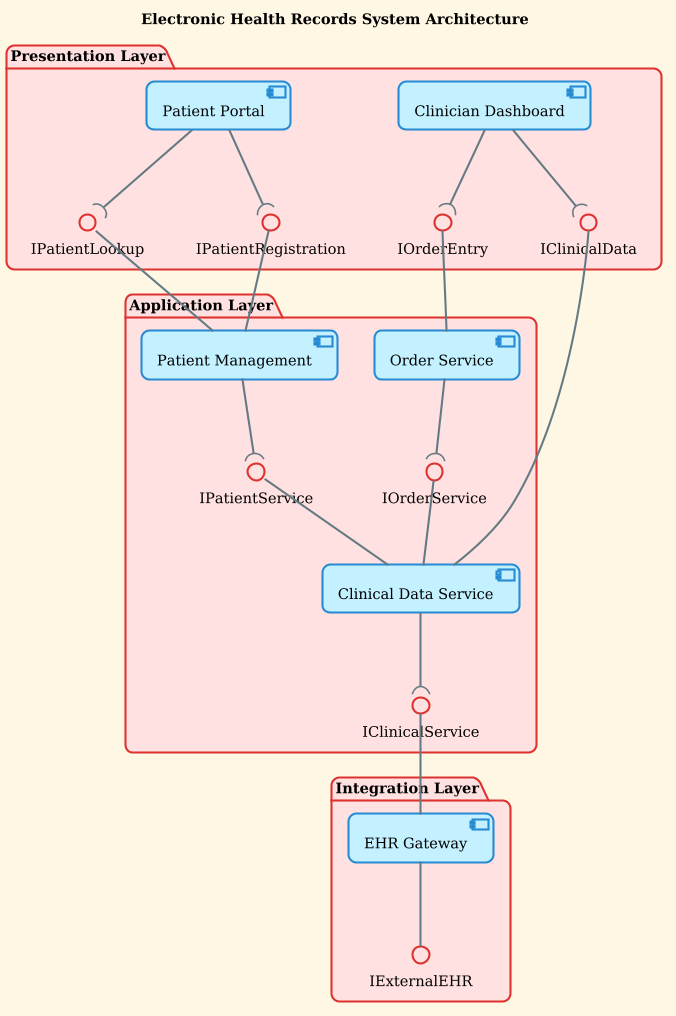
@startuml
!theme sunlust


title Electronic Health Records System Architecture

/'
This diagram presents a simplified architecture of an Electronic Health Records (EHR) System.
It focuses on the core clinical and patient management functions, organized into three layers.
Each interface is co-located with the component that provides it, and required interfaces
are shown as sockets on the consuming component's right side.
'/


package "Presentation Layer" {
    component "Patient Portal" as PP
    interface "IPatientRegistration" as IPReg
    interface "IPatientLookup" as IPLook

    component "Clinician Dashboard" as CD
    interface "IClinicalData" as ICD
    interface "IOrderEntry" as IOE
}

package "Application Layer" {
    component "Patient Management" as PM
    interface "IPatientService" as IPS

    component "Clinical Data Service" as CDS
    interface "IClinicalService" as ICS

    component "Order Service" as OS
    interface "IOrderService" as IOS
}

package "Integration Layer" {
    component "EHR Gateway" as EHRG
    interface "IExternalEHR" as IExtEHR
}

' Presentation to Application - Provided interfaces on left
PP --( IPReg
IPReg -- PM

PP --( IPLook
IPLook -- PM

CD --( ICD
ICD -- CDS

CD --( IOE
IOE -- OS

' Application internal - Required interfaces on right using (
PM --( IPS
IPS -- CDS

OS --( IOS
IOS -- CDS

CDS --( ICS
ICS -- EHRG

' Integration
EHRG -- IExtEHR

@endumlStep-by-Step Architectural Walkthrough
Phase 1: Canvas Configuration & Layout Directives
Every PlantUML diagram begins with setup directives. We start by defining the theme to ensure the diagram looks professional and consistent with the VPasCode branding.
We also set the title and add a comment block to explain the diagram’s context. Comments in PlantUML start with / and end with /, allowing you to write multi-line documentation directly in the code.
@startuml
!theme sunlust

title Electronic Health Records System Architecture

/'
This diagram presents a simplified architecture of an Electronic Health Records (EHR) System.
It focuses on the core clinical and patient management functions, organized into three layers.
'/
Phase 2: Declaring Core Entities, Actors, and Boundaries
Next, we organize the system into packages. Packages act as architectural containers, grouping related components together. In this healthcare scenario, we use packages to represent the standard three-tier architecture: Presentation, Application, and Integration.
package "Presentation Layer" {
    component "Patient Portal" as PP
    interface "IPatientRegistration" as IPReg
    interface "IPatientLookup" as IPLook
    ...
}

package "Application Layer" {
    component "Patient Management" as PM
    ...
}
Inside each package, we define components (the functional units) and interfaces (the contracts they expose). We use the as keyword to assign short aliases (like PP or PM) to keep the connection lines readable.
Phase 3: Mapping Data Flows & Key Interactions
The core of the component diagram lies in defining how components interact. In PlantUML, we distinguish between Provided Interfaces (the service a component offers) and Required Interfaces (the service a component needs).
Provided Interfaces: These are drawn on the left side of the consuming component. We use the -- connector with a socket shape ( on the left.
PP --( IPReg
IPReg -- PM
This syntax indicates that the Patient Portal (PP) requires the IPReg interface, which is provided by the Patient Management component (PM).
Required Interfaces: These are drawn on the right side of the consuming component. We use the ( shape on the right side of the component.
PM --( IPS
IPS -- CDS
This indicates that Patient Management requires the IPatientService interface provided by the Clinical Data Service.
Phase 4: Grouping, Annotations & Visual Polish
Finally, we ensure the diagram is visually clean. We add comments (prefixed with ') to explain specific connection patterns, such as the Application internal flows. This keeps the code self-documenting and ensures that future maintainers understand the architectural intent without needing to reverse-engineer the diagram.
Syntax & Keyword Deep Dive
To master VPasCode and PlantUML, you must understand the specific syntax used to define relationships and structure.
package "Name": Creates a container for grouping related components. Essential for organizing large systems into layers.component "Name": Defines a functional unit of the system. It represents a deployable or logical component.interface "Name": Defines a contract. Interfaces allow components to interact without knowing each other’s internal implementation.--: The standard connector line representing a relationship or dependency.--(: Represents a Required Interface (socket) on the left side of the component. It indicates the component needs this interface to function.--): Represents a Provided Interface (socket) on the right side of the component. It indicates the component offers this interface.!theme: A directive to load a visual theme from the PlantUML standard library./' ... '/: A multi-line comment block used for documentation and context within the diagram.
Best Practices & Pitfalls to Avoid
When building architectural diagrams in VPasCode, follow these guidelines to ensure your models remain maintainable and clear:
- Co-locate Interfaces with Components: Always define the interface inside the same package as the component that provides it. This visually reinforces ownership and responsibility.
- Use Meaningful Aliases: Use short, consistent aliases (e.g.,
PP,PM) for long component names to keep connection lines clean and readable. - Layer Separation: Strictly separate layers (Presentation, Application, Integration) into distinct packages. Avoid crossing layer boundaries in unexpected ways unless intentional.
- Document Intent: Use comment blocks to explain complex flows or architectural decisions. Code comments are often the first thing future developers read.
Try It Yourself with VPasCode
Start Building EHR System Diagrams Faster with VPasCode
Instantly render and customize your Electronic Health Records architecture online in VPasCode without installing any tools.