


Healthcare systems require rigorous documentation to ensure patient safety and operational efficiency. A Genetic Testing and Counseling System involves complex interactions between patients, medical professionals, laboratories, and administrative processes. Visualizing this architecture through a class diagram helps stakeholders understand data relationships, entity responsibilities, and system boundaries before implementation begins.
Diagramming-as-code with PlantUML in VPasCode brings architectural clarity and living documentation to these critical workflows. Unlike static drawing tools, code-based modeling allows teams to iterate quickly, maintain consistency across large systems, and generate diagrams directly from the source. This approach ensures that the visual representation remains synchronized with the actual software design, reducing documentation debt.

Understanding the Model: Purpose, Scope & Problem Framing
Diagram Abstraction & Representation
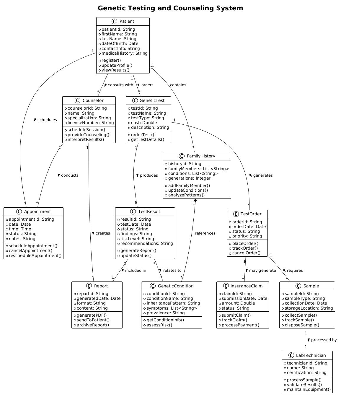
A class diagram in the PlantUML format serves as the structural blueprint for object-oriented software systems. In the context of healthcare, it maps out the static relationships between key entities such as Patients, Counselors, and Test Orders. This visualization clarifies how data flows between actors and objects, defining responsibilities for each class and how they aggregate or compose one another.
Target Domain Scope & Scenario
This guide focuses on a Genetic Testing and Counseling System. The scope covers the entire lifecycle from patient registration and test ordering to sample collection, result generation, and counseling sessions. The diagram encapsulates critical healthcare data points, including medical history, family history, genetic conditions, and insurance claims, ensuring all necessary components for a compliant system are modeled.
Key Takeaways & Educational Insights
By following this tutorial, you will gain insights into modeling complex healthcare workflows using PlantUML. You will learn how to define attributes and methods for various entities, establish cardinality relationships (one-to-many, many-to-many), and apply composition versus aggregation to represent ownership and lifecycle dependencies accurately.
Complete Diagram & Full Source Code
Below is the complete PlantUML source code for the Genetic Testing and Counseling System class diagram. You can copy this code directly into the VPasCode editor to render the diagram instantly.
@startuml
!theme plain
title Genetic Testing and Counseling System

/'
This system manages genetic testing processes and counseling services.
It handles patient information, genetic tests, test results, counselor interactions,
and family history tracking to provide comprehensive genetic health assessments
and personalized counseling recommendations.
'/


class Patient {
    +patientId: String
    +firstName: String
    +lastName: String
    +dateOfBirth: Date
    +contactInfo: String
    +medicalHistory: String
    +register()
    +updateProfile()
    +viewResults()
}

class Counselor {
    +counselorId: String
    +name: String
    +specialization: String
    +licenseNumber: String
    +scheduleSession()
    +provideCounseling()
    +interpretResults()
}

class GeneticTest {
    +testId: String
    +testName: String
    +testType: String
    +cost: Double
    +description: String
    +orderTest()
    +getTestDetails()
}

class TestResult {
    +resultId: String
    +testDate: Date
    +status: String
    +findings: String
    +riskLevel: String
    +recommendations: String
    +generateReport()
    +updateStatus()
}

class FamilyHistory {
    +historyId: String
    +familyMembers: List<String>
    +conditions: List<String>
    +generations: Integer
    +addFamilyMember()
    +updateConditions()
    +analyzePatterns()
}

class Appointment {
    +appointmentId: String
    +date: Date
    +time: Time
    +status: String
    +notes: String
    +scheduleAppointment()
    +cancelAppointment()
    +rescheduleAppointment()
}

class GeneticCondition {
    +conditionId: String
    +conditionName: String
    +inheritancePattern: String
    +symptoms: List<String>
    +prevalence: String
    +getConditionInfo()
    +assessRisk()
}

class TestOrder {
    +orderId: String
    +orderDate: Date
    +status: String
    +priority: String
    +placeOrder()
    +trackOrder()
    +cancelOrder()
}

class Report {
    +reportId: String
    +generatedDate: Date
    +format: String
    +content: String
    +generatePDF()
    +sendToPatient()
    +archiveReport()
}

class InsuranceClaim {
    +claimId: String
    +submissionDate: Date
    +amount: Double
    +status: String
    +submitClaim()
    +trackClaim()
    +processPayment()
}

class LabTechnician {
    +technicianId: String
    +name: String
    +certification: String
    +processSample()
    +validateResults()
    +maintainEquipment()
}

class Sample {
    +sampleId: String
    +sampleType: String
    +collectionDate: Date
    +storageLocation: String
    +collectSample()
    +trackSample()
    +disposeSample()
}

Patient "1" -- "*" GeneticTest : orders >
Patient "1" -- "*" Appointment : schedules >
Patient "*" -- "*" Counselor : consults with >

GeneticTest "1" -- "1" TestResult : produces >
GeneticTest "1" -- "*" TestOrder : generates >

Counselor "1" -- "*" Appointment : conducts >
Counselor "1" -- "*" Report : creates >

TestResult "1" -- "1" Report : included in >
TestResult "*" -- "*" GeneticCondition : relates to >

TestOrder "1" -- "1" Sample : requires >
TestOrder "1" -- "1" InsuranceClaim : may generate >

Sample "1" -- "1" LabTechnician : processed by >

Patient "1" o-- "*" FamilyHistory : contains
FamilyHistory "1" *-- "*" GeneticCondition : references

@endumlStep-by-Step Architectural Walkthrough
Now that you have the full source code, let’s break down the construction of this diagram into logical phases. This walkthrough explains the architectural decisions made in the code.
Phase 1: Canvas Configuration & Layout Directives
Every PlantUML diagram begins with setup directives that define the rendering environment. In this healthcare scenario, we use the !theme plain directive to ensure a clean, professional look suitable for medical documentation. We also define the diagram title and add a comment block using the /' and /' syntax to provide context for future readers.
@startuml
!theme plain
title Genetic Testing and Counseling System

/'
This system manages genetic testing processes...
'/
Phase 2: Declaring Core Entities, Actors, and Boundaries
The core of the class diagram consists of the class definitions. In a healthcare system, entities like Patient, Counselor, and GeneticTest are fundamental. Each class is defined with its attributes (data fields) and methods (behaviors). For example, the Patient class includes sensitive data like medicalHistory and actions like register().
class Patient {
    +patientId: String
    +firstName: String
    +lastName: String
    +register()
    +updateProfile()
}
Phase 3: Mapping Data Flows & Key Interactions
Relationships define how classes interact. We use standard association arrows (--) to show connections. For instance, a Patient orders Genetic Tests. We also define cardinality using numbers and asterisks. A Patient can order many Tests, represented as "1" -- "*". This clarifies the multiplicity of relationships within the system.
Patient "1" -- "*" GeneticTest : orders >
Patient "1" -- "*" Appointment : schedules >
Phase 4: Grouping, Annotations & Visual Polish
To represent ownership and lifecycle dependencies, we use composition (*--) and aggregation (o--). The FamilyHistory class composes GeneticCondition references, indicating a strong lifecycle dependency. Finally, we ensure all relationships are labeled clearly to explain the nature of the interaction, such as consults with or produces.
Syntax & Keyword Deep Dive
Understanding the specific PlantUML syntax is crucial for building robust diagrams. Here are the key keywords and conventions used in this tutorial:
class: Defines a new class entity with its name and body. Used to represent objects likePatientorReport.+: Indicates a public attribute or method visibility modifier within a class definition.--: Represents a standard association line between two classes.o--: Represents aggregation, a “has-a” relationship where the child can exist independently of the parent.*--: Represents composition, a stronger “part-of” relationship where the child’s lifecycle depends on the parent."1" -- "*": Defines cardinality, specifying that one instance of the left class relates to many instances of the right class./'and/': Syntax for multi-line comments that appear in the diagram description.title: Sets the main title of the diagram, visible at the top.!theme plain: Applies a specific visual theme to the rendered diagram for a consistent look.
Best Practices & Pitfalls to Avoid
When modeling complex healthcare systems, adhering to best practices ensures your diagram remains maintainable and clear.
- Keep Diagrams Modular: Avoid creating a single massive class diagram. If the system is large, consider splitting into subsystems (e.g., Patient Management vs. Lab Operations).
- Use Descriptive Names: Class names should be nouns (e.g.,
TestOrder) and methods should be verbs (e.g.,generateReport()). - Manage Visual Complexity: If relationships become tangled, use grouping or packages to organize related classes together visually.
- Consistent Abstraction: Decide early on whether your diagram is high-level (conceptual) or low-level (implementation details) and stick to that level throughout.
Try It Yourself with VPasCode
Start Building PlantUML Diagrams Faster with VPasCode
Test, preview, and customize this Genetic Testing System diagram instantly in your browser with our free PlantUML editor—no installation required.