


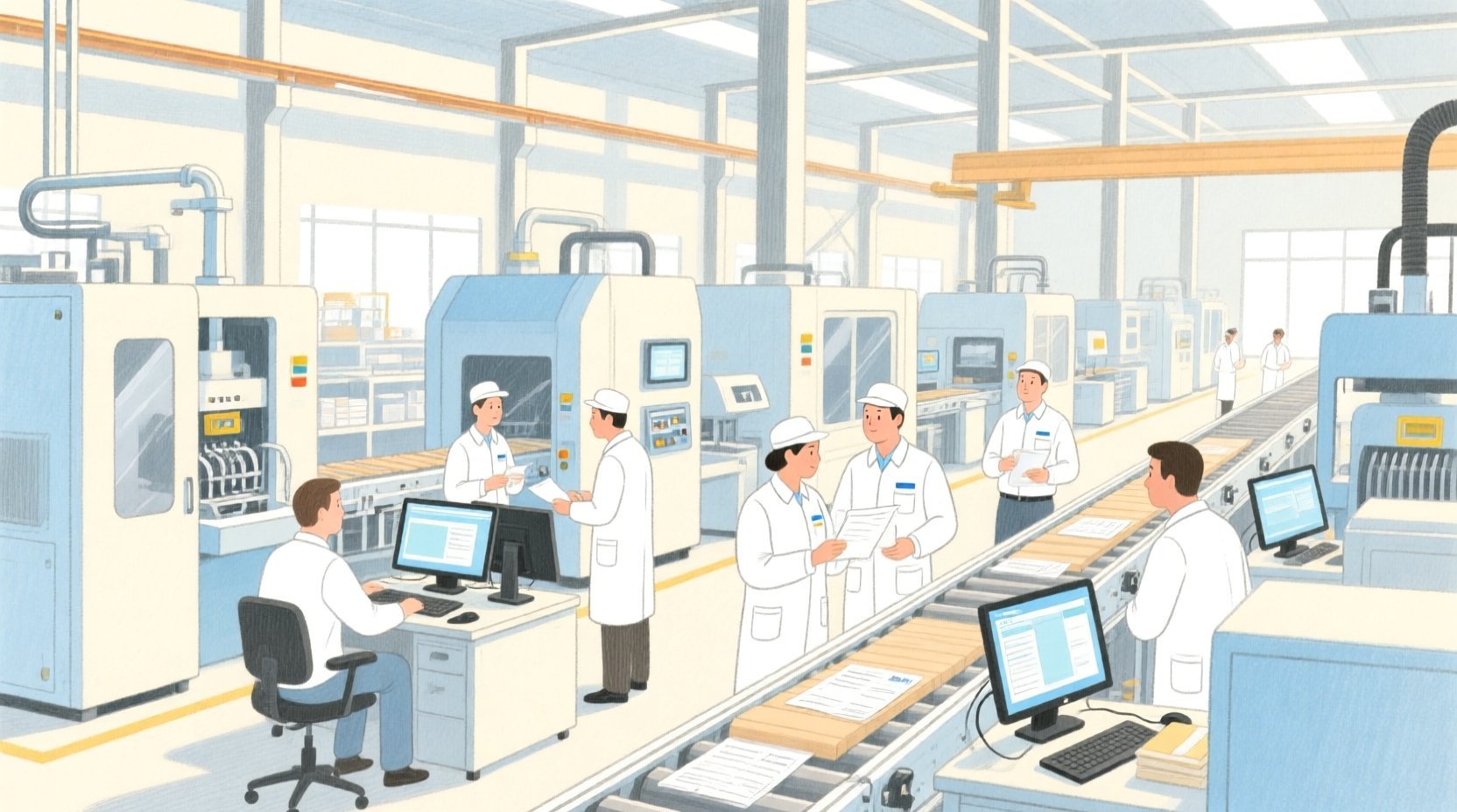
In modern industrial operations, the gap between high-level planning (ERP) and shop-floor execution is often bridged by a Manufacturing Execution System (MES). Designing the data model for an MES is a complex challenge. It requires capturing the intricate relationships between physical resources (machines, operators), abstract plans (work orders, routings), and real-time execution data (steps, quality checks).
Traditional drag-and-drop modeling tools often struggle with the complexity of these domain models, leading to cluttered diagrams and diagram-as-code modeling nightmares. Diagram-as-code using PlantUML offers a superior alternative for software architects. It allows you to define your domain logic in a structured text format that is easy to review, maintain, and version.
VPasCode, the free web-based diagram editor by Visual Paradigm, brings this power to your browser instantly. With zero local installation, you can write, render, and refine your MES architecture in real time. This tutorial serves as a masterclass on building a professional-grade Class Diagram for an MES, demonstrating how to structure entities, define relationships, and visualize the lifecycle of a production job.
Understanding the Model: Purpose, Scope & Problem Framing
Before diving into the syntax, it is critical to understand the domain abstraction we are modeling.
Diagram Abstraction & Representation
This is a Class Diagram, which models the static structure of the system. Unlike sequence diagrams that show time, or flowcharts that show logic, a class diagram defines the things that exist in the system and how they relate to each other. In the context of an MES, these “things” are:
- Production Definitions: What are we making? (WorkOrders, Routings, Operations)
- Production Resources: Who or what is making it? (WorkCenters, Equipment, Operators)
- Execution Records: What actually happened? (ProductionSteps, MaterialLots)
- Quality Feedback: Did it meet standards? (QualityChecks, Nonconformances)
Target Domain Scope & Scenario
The scope of this diagram covers the Core Domain of a manufacturing workflow. It intentionally excludes external integrations (like ERP or SCADA) to focus on the internal logic of the execution engine. It models the lifecycle from a WorkOrder creation, through its decomposition into Operations, to the actual execution on a machine by an operator, including material consumption and quality validation.
Key Takeaways & Educational Insights
By the end of this guide, you will understand how to:
- Apply Generalization to model shared resource behaviors.
- Distinguish between Composition (strong ownership) and Aggregation (weak ownership) in manufacturing contexts.
- Model complex Associations that track traceability between materials and production steps.
Complete Diagram & Full Source Code
Below is the finished blueprint for the Manufacturing Execution System. This diagram encapsulates the core entities required to manage production, resources, and quality within a single cohesive model.
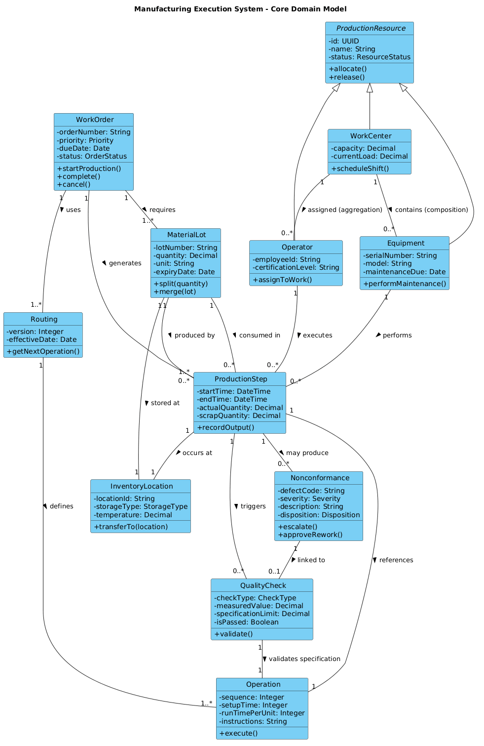
Note: The image above represents the rendered output. To edit this diagram interactively, use the code block below in the VPasCode editor.
@startuml
!include https://static.visual-paradigm.com/web/resources/plantuml-stdlib/themes/vp.puml

title Manufacturing Execution System – Core Domain Model

/'
This class diagram models the core domain of a Manufacturing Execution System (MES)
used to track and control production on the shop floor. The system manages work orders,
routings, operations, material lots, equipment, personnel, and quality checks.
It supports real-time data collection, resource allocation, traceability, and
nonconformance handling. The diagram focuses on the relationships between production
definition (what to make), production resources (who/with what), production execution
(actual jobs and steps), and quality feedback (measurements and defects).
'/

abstract class ProductionResource {
  - id: UUID
  - name: String
  - status: ResourceStatus
  + allocate()
  + release()
}

class WorkCenter {
  - capacity: Decimal
  - currentLoad: Decimal
  + scheduleShift()
}

class Equipment {
  - serialNumber: String
  - model: String
  - maintenanceDue: Date
  + performMaintenance()
}

class Operator {
  - employeeId: String
  - certificationLevel: String
  + assignToWork()
}

class MaterialLot {
  - lotNumber: String
  - quantity: Decimal
  - unit: String
  - expiryDate: Date
  + split(quantity)
  + merge(lot)
}

class WorkOrder {
  - orderNumber: String
  - priority: Priority
  - dueDate: Date
  - status: OrderStatus
  + startProduction()
  + complete()
  + cancel()
}

class Routing {
  - version: Integer
  - effectiveDate: Date
  + getNextOperation()
}

class Operation {
  - sequence: Integer
  - setupTime: Integer
  - runTimePerUnit: Integer
  - instructions: String
  + execute()
}

class ProductionStep {
  - startTime: DateTime
  - endTime: DateTime
  - actualQuantity: Decimal
  - scrapQuantity: Decimal
  + recordOutput()
}

class QualityCheck {
  - checkType: CheckType
  - measuredValue: Decimal
  - specificationLimit: Decimal
  - isPassed: Boolean
  + validate()
}

class Nonconformance {
  - defectCode: String
  - severity: Severity
  - description: String
  - disposition: Disposition
  + escalate()
  + approveRework()
}

class InventoryLocation {
  - locationId: String
  - storageType: StorageType
  - temperature: Decimal
  + transferTo(location)
}

' Relationships

ProductionResource <|-- WorkCenter
ProductionResource <|-- Equipment
ProductionResource <|-- Operator

WorkOrder "1" -- "1..*" Routing : uses >
Routing "1" -- "1..*" Operation : defines >

WorkOrder "1" -- "1..*" ProductionStep : generates >
ProductionStep "1" -- "1" Operation : references >

ProductionStep "1" -- "0..*" QualityCheck : triggers >
ProductionStep "1" -- "0..*" Nonconformance : may produce >

Equipment "1" -- "0..*" ProductionStep : performs >
Operator "1" -- "0..*" ProductionStep : executes >

MaterialLot "1" -- "0..*" ProductionStep : consumed in >
MaterialLot "1" -- "0..*" ProductionStep : produced by >

WorkOrder "1" -- "1..*" MaterialLot : requires >
ProductionStep "1" -- "1" InventoryLocation : occurs at >

Nonconformance "1" -- "0..1" QualityCheck : linked to >
WorkCenter "1" -- "0..*" Equipment : contains (composition) >
WorkCenter "1" -- "0..*" Operator : assigned (aggregation) >

MaterialLot "1" -- "1" InventoryLocation : stored at >

' Additional association
QualityCheck "1" -- "1" Operation : validates specification >
@endumlStep-by-Step Architectural Walkthrough
Let’s break down the construction of this diagram into four logical phases. This approach ensures your model remains organized and semantically accurate.
Phase 1: Canvas Configuration & Layout Directives
Every professional diagram starts with a consistent visual identity. We begin by including the VP theme to ensure the diagram looks polished immediately. We also define the title and a comment block to document the diagram’s intent.
Key Syntax:
!include https://static.visual-paradigm.com/web/resources/plantuml-stdlib/themes/vp.puml

title Manufacturing Execution System – Core Domain Model

/'
This class diagram models the core domain of a Manufacturing Execution System (MES)
... (comment text) ...
'/
The !include directive pulls in the standard PlantUML library for themes. The /' ... '/ block creates a visible documentation note within the diagram, which is essential for team alignment.
Phase 2: Declaring Core Entities, Actors, and Boundaries
Next, we define the classes. In an MES, we have distinct categories of entities: Resources, Plans, and Execution Records.
1. Resource Hierarchy:
We start with an abstract class named ProductionResource. This is a crucial modeling decision. It defines common attributes like id, name, and status that every resource (Machine, Person, Location) shares.
abstract class ProductionResource {
  - id: UUID
  - name: String
  - status: ResourceStatus
  + allocate()
  + release()
}
2. Concrete Resources:
We then define WorkCenter, Equipment, and Operator as concrete classes. They will inherit from the abstract resource later.
3. Production Definitions:
We define WorkOrder (the request), Routing (the path), and Operation (the specific task). These form the “planning” side of the system.
Phase 3: Mapping Data Flows & Key Interactions
Now we define the relationships. In PlantUML, relationships are drawn between classes using lines and arrows. We use specific keywords to denote the nature of the connection.
1. Generalization (Inheritance):
The relationship between ProductionResource and its children is defined using the <|-- symbol. This indicates that a WorkCenter is a ProductionResource.
ProductionResource <|-- WorkCenter
ProductionResource <|-- Equipment
ProductionResource <|-- Operator
2. Composition & Aggregation:
We use the contains and assigned labels to distinguish ownership.
- Composition:
WorkCenter -- Equipmentimplies that Equipment cannot exist without a WorkCenter. If the center is deleted, the equipment is logically removed. - Aggregation:
WorkCenter -- Operatorimplies an Operator can exist independently of a specific WorkCenter (they can be reassigned).
Phase 4: Grouping, Annotations & Visual Polish
The final phase involves linking the execution data (ProductionSteps) to the planning data (Operations) and quality data (QualityChecks). This closes the loop of traceability.
We define the lifecycle of a ProductionStep by linking it to the Operation it executes and the QualityCheck it triggers. This ensures that every step on the shop floor is backed by a defined operation and validated by a quality check.
ProductionStep "1" -- "0..*" QualityCheck : triggers >
ProductionStep "1" -- "0..*" Nonconformance : may produce >
This structure allows architects to visualize the "Happy Path" (successful production) and the "Exception Path" (Nonconformance) within a single diagram.
Syntax & Keyword Deep Dive
To master this diagram, you need to understand the specific PlantUML syntax features used to represent manufacturing concepts.
abstract class: Used forProductionResource. It indicates a template that cannot be instantiated directly but serves as a parent for other classes.<|--(Generalization): The arrow pointing to the parent class. It signifies an "is-a" relationship (e.g., an Operator is-a Resource).--(Association): A solid line connecting two classes. Used for most relationships likeWorkOrderandMaterialLot."1" -- "0..*"(Cardinality): This defines the multiplicity."1"means exactly one, while"0..*"means zero or many. This is critical for defining business rules (e.g., A WorkOrder requires one or more MaterialLots).+and-(Visibility):+denotes public members (methods), while-denotes private attributes.: label(Relationship Label): The text after the colon (e.g.,: uses >) describes the semantic meaning of the line, making the diagram self-documenting.
Best Practices & Pitfalls to Avoid
When modeling complex systems like an MES, keep these architectural guidelines in mind:
- Keep Abstraction Levels Consistent: Do not mix high-level business concepts (like "WorkOrder") with low-level technical implementation details (like "DatabaseID") in the same diagram unless necessary. Focus on the domain model.
- Use Cardinality Wisely: Never leave cardinality ambiguous. In manufacturing, knowing if a step is mandatory ("1") or optional ("0..1") is a critical business rule.
- Separate Planning from Execution: Notice how
Routing(Plan) is separate fromProductionStep(Execution). This separation allows the same plan to be used for multiple actual jobs. - Document Relationships: Always label your lines. A line between
OperatorandEquipmentcould mean "uses", "maintains", or "operates". The label clarifies the intent.
Start Building PlantUML Diagrams Faster with VPasCode
Instantly render your Manufacturing Execution System models in the browser with zero setup, test syntax changes live, and share your diagrams with your team for free.