


In the fast-paced world of online gaming, the user experience hinges on more than just graphics; it relies heavily on the speed and reliability of backend infrastructure. One of the most critical components of a modern multiplayer game is the matchmaking system. This system is responsible for pairing players with similar skill levels in a timely manner, ensuring balanced and engaging gameplay.

Designing such a complex, event-driven system requires precise documentation. Visual modeling serves as the blueprint for development, allowing engineers to trace the flow of data between the client, the matchmaking service, and the game servers. A sequence diagram is the ideal tool for this purpose, as it captures the chronological order of interactions and the state of objects over time.
By using PlantUML within VPasCode, game architects can rapidly prototype these workflows without the overhead of traditional GUI tools. This approach enables immediate visualization of logic branches, such as successful matches, lobby creation, or timeout scenarios, ensuring that the architecture is robust before a single line of backend code is written.
Understanding the Model: Purpose, Scope & Problem Framing
Diagram Abstraction & Representation
A sequence diagram models the dynamic behavior of a system by showing how objects interact over time. In the context of this tutorial, we are modeling a multiplayer matchmaking scenario. This diagram abstraction is crucial because it highlights:
- Temporal Flow: The exact order in which messages are sent (e.g., Player Request -> Client -> Matchmaking Service).
- Activation Durations: How long an object (like the Matchmaking Service) remains active to process a request.
- Alternative Paths: What happens if a lobby isn’t found immediately, or if the player cancels.
Target Domain Scope & Scenario
This model focuses specifically on the entertainment and gaming industry domain. The scope is defined by the following system boundaries:
- Input: A player selects a game mode and initiates a search.
- Processing: The Matchmaking Service queries the Player Database, checks for existing lobbies, or creates new ones.
- Output: The Game Client receives server details and connects to the Game Server.
- Exclusions: This diagram does not cover the actual gameplay loop or client-side rendering logic, focusing strictly on the connection establishment phase.
Key Takeaways & Educational Insights
By constructing this diagram, you will gain insights into:
- How to structure a complex, multi-step interaction using combined fragments like
altandloop. - How to represent asynchronous callbacks (e.g.,
DB --> MM). - How to manage visual complexity by grouping related actions under logical headers.
Complete Diagram & Full Source Code
Below is the complete blueprint for the Multiplayer Matchmaking Scenario. This diagram utilizes the aws-orange theme to provide a clean, professional aesthetic suitable for technical documentation.
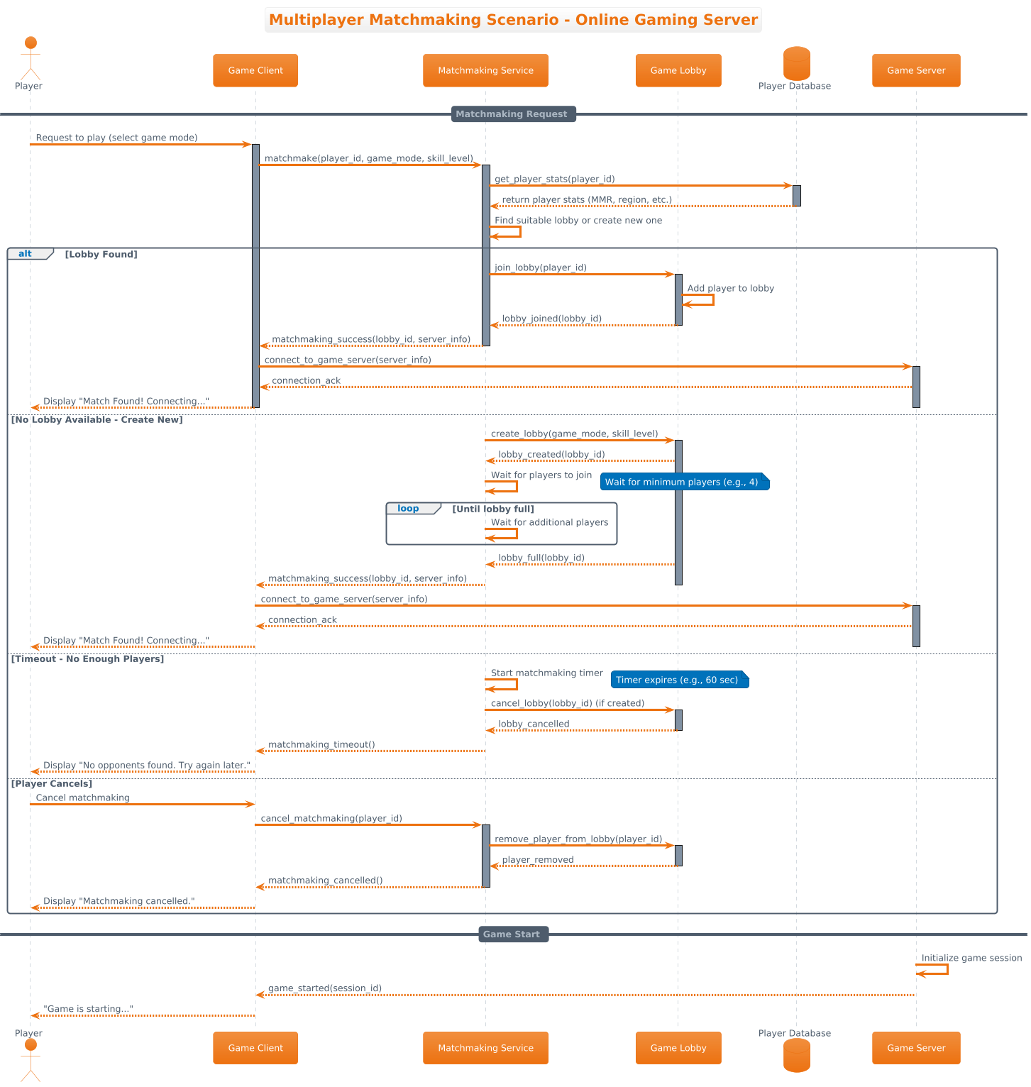
Below is the full source code. You can copy this directly into the VPasCode editor to render it instantly.
@startuml
!theme aws-orange

title Multiplayer Matchmaking Scenario - Online Gaming Server

/'
This sequence diagram illustrates the matchmaking process for an online multiplayer game.
It covers player request, lobby creation, matchmaking service logic, and alternative flows
for success, timeout, and cancellation scenarios.
'/

actor "Player" as P
participant "Game Client" as GC
participant "Matchmaking Service" as MM
participant "Game Lobby" as GL
database "Player Database" as DB
participant "Game Server" as GS

== Matchmaking Request ==
P -> GC: Request to play (select game mode)
activate GC
GC -> MM: matchmake(player_id, game_mode, skill_level)
activate MM
MM -> DB: get_player_stats(player_id)
activate DB
DB --> MM: return player stats (MMR, region, etc.)
deactivate DB

MM -> MM: Find suitable lobby or create new one

alt Lobby Found
    MM -> GL: join_lobby(player_id)
    activate GL
    GL -> GL: Add player to lobby
    GL --> MM: lobby_joined(lobby_id)
    deactivate GL
    MM --> GC: matchmaking_success(lobby_id, server_info)
    deactivate MM
    GC -> GS: connect_to_game_server(server_info)
    activate GS
    GS --> GC: connection_ack
    GC --> P: Display "Match Found! Connecting..."
    deactivate GS
    deactivate GC

else No Lobby Available - Create New
    MM -> GL: create_lobby(game_mode, skill_level)
    activate GL
    GL --> MM: lobby_created(lobby_id)
    MM -> MM: Wait for players to join
    note right: Wait for minimum players (e.g., 4)

    loop Until lobby full
        MM -> MM: Wait for additional players
    end

    GL --> MM: lobby_full(lobby_id)
    MM --> GC: matchmaking_success(lobby_id, server_info)
    deactivate MM
    deactivate GL
    GC -> GS: connect_to_game_server(server_info)
    activate GS
    GS --> GC: connection_ack
    GC --> P: Display "Match Found! Connecting..."
    deactivate GS
    deactivate GC

else Timeout - No Enough Players
    MM -> MM: Start matchmaking timer
    note right: Timer expires (e.g., 60 sec)
    MM -> GL: cancel_lobby(lobby_id) (if created)
    activate GL
    GL --> MM: lobby_cancelled
    deactivate GL
    MM --> GC: matchmaking_timeout()
    deactivate MM
    GC --> P: Display "No opponents found. Try again later."
    deactivate GC

else Player Cancels
    P -> GC: Cancel matchmaking
    GC -> MM: cancel_matchmaking(player_id)
    activate MM
    MM -> GL: remove_player_from_lobby(player_id)
    activate GL
    GL --> MM: player_removed
    deactivate GL
    MM --> GC: matchmaking_cancelled()
    deactivate MM
    GC --> P: Display "Matchmaking cancelled."
    deactivate GC

end

== Game Start ==
GS -> GS: Initialize game session
GS --> GC: game_started(session_id)
GC --> P: "Game is starting..."
@endumlStep-by-Step Architectural Walkthrough
Building a robust sequence diagram requires a structured approach. We will deconstruct the diagram into four distinct phases to understand how each component contributes to the final visualization.
Phase 1: Canvas Configuration & Layout Directives
Before defining the actors, we must set the visual theme and the title of the diagram. This ensures consistency across your documentation.
- Theme: We use
!theme aws-orangeto apply a modern, warm color palette suitable for professional technical presentations. - Title: The
titledirective clearly labels the diagram’s purpose. - Comment Block: We use
/' ... '/to add a multi-line description that explains the diagram’s scope without rendering as a visual element.
!theme aws-orange

title Multiplayer Matchmaking Scenario - Online Gaming Server

/'
This sequence diagram illustrates the matchmaking process...
'/
Phase 2: Declaring Core Entities, Actors, and Boundaries
The next step is defining the participants. In a sequence diagram, every object that sends or receives a message must be declared.
- Actors: The
actorkeyword represents human users (e.g., thePlayer). - Participants: The
participantkeyword represents software components (e.g.,Game Client,Matchmaking Service,Game Server). - Databases: The
databasekeyword is used for persistent storage (e.g.,Player Database).
actor "Player" as P
participant "Game Client" as GC
participant "Matchmaking Service" as MM
participant "Game Lobby" as GL
database "Player Database" as DB
participant "Game Server" as GS
We assign short aliases (like P, GC, MM) to make the interaction lines cleaner and easier to read.
Phase 3: Mapping Data Flows & Key Interactions
This is the core logic of the diagram. We define the sequence of events using arrow notation.
- Synchronous Messages: Solid arrows (
->) indicate a request that expects a response. - Asynchronous Responses: Dashed arrows (
-->) indicate a return value or callback. - Self-Reference: Arrows pointing to the same participant (
MM -> MM) represent internal processing logic.
GC -> MM: matchmake(player_id, game_mode, skill_level)
activate MM
MM -> DB: get_player_stats(player_id)
activate DB
DB --> MM: return player stats (MMR, region, etc.)
debactivate DB
Phase 4: Grouping, Annotations & Visual Polish
To handle complex logic like retries, timeouts, or user cancellations, we use combined fragments.
- Alt (Alternative): The
altblock splits the flow into mutually exclusive paths (e.g., Lobby Found vs. Timeout). - Loop: The
loopblock represents repeated actions, such as waiting for players to fill a lobby. - Notes: The
notedirective adds explanatory text to specific points in the timeline.
alt Lobby Found
    ...
else No Lobby Available - Create New
    ...
    loop Until lobby full
        ...
    end
end
Syntax & Keyword Deep Dive
To master PlantUML, it is essential to understand the specific syntax keywords used in this diagram.
actor: Defines a human user or external entity initiating the interaction.participant: Defines a software component or service that processes data.database: Specifically renders a storage component, distinguishing it from active services.activate/deactivate: These keywords draw the vertical “activation bar” on the lifeline, showing exactly when an object is busy processing a request.-->(Dashed Arrow): Represents a return message or asynchronous event. It is crucial for showing data coming back from the database or confirming a connection.alt/else/end: These keywords create a decision boundary. The diagram will render distinct boxes for each alternative path.note right: Attaches a text annotation to the right side of a lifeline for quick context.
Best Practices & Pitfalls to Avoid
When creating sequence diagrams with VPasCode, keep these architectural best practices in mind to ensure your diagrams remain maintainable and clear.
- Limit Scope per Diagram: Do not try to model every single API call in a massive system. Focus on the critical path (e.g., Matchmaking) and create separate diagrams for other flows (e.g., Inventory Management).
- Consistent Naming: Use clear, descriptive names for participants. Avoid vague terms like
SystemorObj1. UseMatchmaking ServiceorPlayer Databaseinstead. - Manage Visual Complexity: If an
altblock becomes too deep or nested, consider splitting it into multiple diagrams. Deep nesting makes the diagram hard to read. - Use Aliases Wisely: Short aliases (like
GC) are great for readability, but ensure they are defined clearly at the top of the diagram so new readers understand the context.
Try It Yourself with VPasCode
Start Building PlantUML Diagrams Faster with VPasCode
Test, preview, and customize this multiplayer matchmaking diagram instantly in your browser with VPasCode’s free PlantUML editor—no installation required.