


In the fast-paced environment of modern retail, operational efficiency is paramount. Every interaction at the Point-of-Sale (POS) terminal, from a new sale to a complex return, impacts customer satisfaction and inventory accuracy. When processes become convoluted, errors occur, and customer trust erodes. This is where visual modeling becomes a critical architectural tool.

An Activity Diagram is one of the most effective ways to map out these operational workflows. It provides a clear, step-by-step visualization of the logic, decision points, and parallel tasks involved in a business process. For a retail scenario like a product return, clarity is essential to ensure cashiers follow the correct protocol, systems update accurately, and customers receive fair treatment.
By using PlantUML within the VPasCode web editor, software architects and retail system designers can rapidly prototype these workflows without the overhead of heavy desktop software. This approach, known as diagram-as-code, allows teams to treat their process maps as living documentation that can be versioned, shared, and iterated upon instantly in the browser. In this masterclass, we will construct a professional POS Return Process activity diagram, demonstrating how to handle swimlanes, conditional logic, and parallel processing.
Understanding the Model: Purpose, Scope & Problem Framing
Before diving into the syntax, it is crucial to understand the architectural abstraction we are building. This diagram is not merely a list of steps; it is a representation of the interaction between human actors and automated systems.
Diagram Abstraction & Representation
The Activity Diagram is chosen here because it excels at modeling control flow. Unlike a flowchart, which is often static, a PlantUML activity diagram can represent complex behaviors such as:
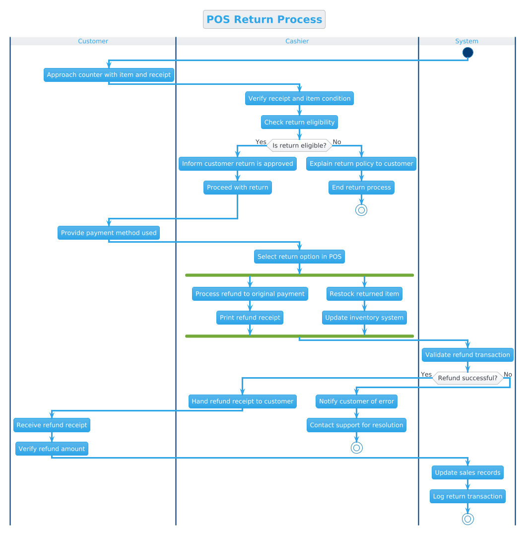
- Swimlanes: Separating responsibilities between the Customer, Cashier, and System to clarify who performs which action.
- Conditional Logic: Handling decision points like “Is return eligible?” or “Refund successful?” which branch the workflow into different paths.
- Parallel Flows: Simultaneous actions, such as processing a refund while updating inventory, which occur at the same time.
Target Domain Scope & Scenario
This model specifically covers the Return Process at a retail POS terminal. The scope is bounded by the moment the customer approaches the counter to the final logging of the transaction. It intentionally excludes backend ERP integrations or external payment gateway API calls, focusing instead on the immediate operational flow within the store environment.
Key Takeaways & Educational Insights
By studying this model, readers will gain insight into:
- How to define clear boundaries for system interactions using swimlanes.
- How to implement robust error handling (e.g., refund failures) within a visual workflow.
- How to optimize process efficiency by identifying parallel tasks that can reduce wait times.
Complete Diagram & Full Source Code
Below is the complete blueprint for the POS Return Process. This diagram utilizes the Cerulean theme for a clean, professional appearance and leverages PlantUML’s activity diagram syntax to define the flow.
@startuml
!theme cerulean
title POS Return Process

|Customer|
|Cashier|
|System|

start

|Customer|
:Approach counter with item and receipt;

|Cashier|
:Verify receipt and item condition;
:Check return eligibility;

if (Is return eligible?) then (Yes)
  :Inform customer return is approved;
  :Proceed with return;
else (No)
  :Explain return policy to customer;
  :End return process;
  stop
endif

|Customer|
:Provide payment method used;

|Cashier|
:Select return option in POS;

fork
  :Process refund to original payment;
  :Print refund receipt;
fork again
  :Restock returned item;
  :Update inventory system;
end fork

|System|
:Validate refund transaction;

if (Refund successful?) then (Yes)
  |Cashier|
  :Hand refund receipt to customer;
  |Customer|
  :Receive refund receipt;
  :Verify refund amount;
else (No)
  |Cashier|
  :Notify customer of error;
  :Contact support for resolution;
  stop
endif

|System|
:Update sales records;
:Log return transaction;

stop
@endumlStep-by-Step Architectural Walkthrough
Building this diagram in VPasCode involves four distinct phases: configuring the canvas, defining the actors, mapping the logic, and polishing the visual flow.
Phase 1: Canvas Configuration & Layout Directives
Every PlantUML diagram begins with global directives that set the visual tone. In this scenario, we want a professional look suitable for business documentation.
We start by applying the Cerulean theme, which provides a clean blue-toned aesthetic. We also define a Title to clearly identify the diagram’s purpose.
!theme cerulean
title POS Return Process
Next, we establish the Swimlanes. Swimlanes are crucial for activity diagrams as they assign responsibility. We define three lanes: |Customer|, |Cashier|, and |System|. This immediately tells the reader which entity initiates and completes each step.
Phase 2: Declaring Core Entities, Actors, and Boundaries
The workflow begins with the start node. In PlantUML, this is the entry point of the activity.
We then map the initial interactions. Notice how the swimlane switches are handled. To perform an action in a specific lane, you simply reference the lane name again before the action.
|Customer|
:Approach counter with item and receipt;

|Cashier|
:Verify receipt and item condition;
:Check return eligibility;
This structure ensures that the diagram visually tracks the hand-off of responsibility from the customer to the staff member.
Phase 3: Mapping Data Flows & Key Interactions
The core logic of the return process involves decision points. We use the if statement syntax to model eligibility checks.
if (Is return eligible?) then (Yes)
  :Inform customer return is approved;
  :Proceed with return;
else (No)
  :Explain return policy to customer;
  :End return process;
  stop
endif
This block demonstrates branching logic. If the condition is met, the flow continues. If not, it triggers an error path leading to a stop node. This is critical for modeling real-world constraints where processes must terminate gracefully.
Phase 4: Grouping, Annotations & Visual Polish
Complex retail processes often require parallel tasks. For example, while the cashier processes the money, the system should update stock. PlantUML handles this with the fork directive.
fork
  :Process refund to original payment;
  :Print refund receipt;
fork again
  :Restock returned item;
  :Update inventory system;
end fork
This syntax creates two parallel branches that execute simultaneously and merge at the end fork point. This visualizes concurrency, showing that inventory updates do not block the refund issuance.
Syntax & Keyword Deep Dive
To customize and extend this diagram, it is essential to understand the specific PlantUML syntax features utilized in this model.
!theme cerulean: A directive that applies a predefined color scheme to the entire diagram, ensuring consistency with corporate branding or documentation standards.|Swimlane Name|: Defines a horizontal or vertical lane. Actions following this tag belong to that specific actor until another lane is declared.:Action Text;: Represents an activity or process step. The colon indicates an activity, and the semicolon marks the end of the statement.if (Condition) then (Label): Creates a decision node. The text inside parentheses is the condition, and the label indicates the path taken if true.fork ... fork again ... end fork: Initiates parallel processing. Tasks inside these blocks run concurrently and synchronize at the end.startandstop: Marks the entry and exit points of the activity flow. Multiplestopnodes are allowed for different termination conditions.
Best Practices & Pitfalls to Avoid
When designing activity diagrams for complex systems like POS terminals, keep these best practices in mind to maintain clarity and maintainability.
- Keep Swimlanes Balanced: Ensure each lane has a logical workload. If one lane (like System) has too many steps compared to others, it may indicate a need to refactor the process or split the diagram.
- Limit Decision Depth: Avoid nesting
ifstatements too deeply (e.g., if inside an if). This creates a “spaghetti diagram” that is hard to read. If a decision is complex, consider splitting it into sub-activities. - Use Clear Labels: In
ifstatements, explicitly label the paths (e.g.,then (Yes)andelse (No)). This prevents ambiguity for anyone reviewing the diagram later. - Handle Error Paths Explicitly: Never assume a process will always succeed. Always model the
elsebranch for critical operations like refunds to show how the system handles failures.
Try It Yourself with VPasCode
Start Building PlantUML Activity Diagrams Faster with VPasCode
Instantly prototype retail workflows and POS processes online with VPasCode, our free PlantUML editor that renders diagrams live in your browser without any installation.