


In the high-stakes realm of telecommunications and national security, the integrity of data modeling is not merely a technical requirement but a legal imperative. Lawful interception systems serve as the digital backbone for judicial oversight, managing the delicate balance between privacy rights and the necessity for intelligence gathering. These systems must rigorously track the lifecycle of warrants, from judicial issuance to the final destruction of retained content, ensuring every action is logged, authorized, and auditable. A single flaw in the data architecture can lead to compliance failures, legal challenges, or the loss of critical evidence.

Designing an Entity Relationship Diagram (ERD) for such a complex ecosystem requires a level of precision that traditional drag-and-drop tools often struggle to maintain as the schema evolves. Diagram-as-code approaches, specifically using PlantUML, allow architects to version their data models, enforce strict naming conventions, and visualize complex cardinalities with mathematical accuracy. By leveraging VPasCode, a free web-based diagram editor, telecommunications architects can rapidly prototype these intricate schemas, instantly rendering the relationships between legal authorities, law enforcement agencies, service providers, and the sensitive communication content they manage.
Understanding the Model: Purpose, Scope & Problem Framing
The diagram presented in this tutorial models the comprehensive data structure for a Lawful Interception Warrant Management and Communication Content Retention System. This is not a simple database schema; it is a representation of a regulated workflow where data integrity, auditability, and legal compliance are paramount.
Diagram Abstraction & Representation
An Entity Relationship Diagram (ERD) is the ideal tool for this problem because it abstracts the physical database implementation into logical relationships that stakeholders can understand. In this context, the diagram maps the critical entities: Legal Authorities (who issue warrants), Law Enforcement Agencies (who request them), Service Providers (who execute the interception), and the Targets (the subjects of the investigation). It further details the Interception Activities, the resulting Communication Content, and the Retention Policies that govern how long this sensitive data is kept before secure destruction.
Target Domain Scope & Scenario
This model covers the full lifecycle of an interception case within a telecommunications environment. It explicitly defines the boundaries between the judicial system (issuing authority), the operational enforcement layer (agencies and users), and the technical execution layer (service providers and retention systems). The scope includes the management of warrant metadata, the tracking of specific communication events (calls, messages), and the rigorous logging of all access to this data to prevent misuse.
Key Takeaways & Educational Insights
By studying this model, you will gain insights into how to structure a system that enforces strict separation of duties. You will learn how to model one-to-many relationships (e.g., one warrant authorizing multiple interception activities) and how to link policy definitions (retention periods) directly to data records. The diagram clarifies the “who, what, when, and why” of data access, ensuring that every piece of retained content can be traced back to a valid legal basis.
Complete Diagram & Full Source Code
Below is the fully rendered ERD. This blueprint visualizes the complex web of relationships required to manage lawful interception in a compliant manner.
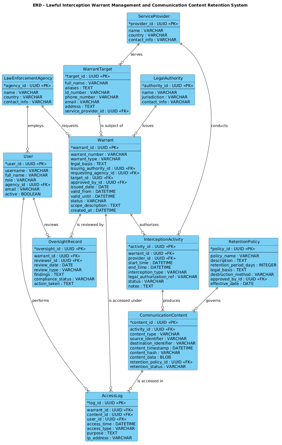
Here is the complete PlantUML source code used to generate this diagram. You can copy this entire block to see the diagram in action.
@startuml
!include https://static.visual-paradigm.com/web/resources/plantuml-stdlib/themes/vp.puml

title ERD - Lawful Interception Warrant Management and Communication Content Retention System

/'
This diagram models the data structure for a lawful interception warrant management and communication content retention system.

The system supports the lifecycle of interception warrants: creating and approving warrants, assigning them to targets, and managing the retention of intercepted communications. It distinguishes between warrant-related metadata (such as judicial authorization, legal basis, issuing authority, and scope) and communication content (such as intercepted calls, messages, and session records). It also captures the roles of legal authorities, law enforcement agencies, telecom service providers, targets, and retention policies. The ERD is intended to clarify the relationships among warrants, targets, interception activities, retained content, access logs, and oversight records.
'/

' =====================
' Core entities
' =====================

entity "LegalAuthority" as LegalAuthority {
  * authority_id : UUID <<PK>>
  --
  name : VARCHAR
  jurisdiction : VARCHAR
  contact_info : VARCHAR
}

entity "LawEnforcementAgency" as LawEnforcementAgency {
  * agency_id : UUID <<PK>>
  --
  name : VARCHAR
  country : VARCHAR
  contact_info : VARCHAR
}

entity "ServiceProvider" as ServiceProvider {
  * provider_id : UUID <<PK>>
  --
  name : VARCHAR
  country : VARCHAR
  contact_info : VARCHAR
}

entity "Warrant" as Warrant {
  * warrant_id : UUID <<PK>>
  --
  warrant_number : VARCHAR
  warrant_type : VARCHAR
  legal_basis : TEXT
  issuing_authority_id : UUID <<FK>>
  requesting_agency_id : UUID <<FK>>
  target_id : UUID <<FK>>
  approved_by_id : UUID <<FK>>
  issued_date : DATE
  valid_from : DATETIME
  valid_until : DATETIME
  status : VARCHAR
  scope_description : TEXT
  created_at : DATETIME
}

entity "WarrantTarget" as WarrantTarget {
  * target_id : UUID <<PK>>
  --
  full_name : VARCHAR
  aliases : TEXT
  id_number : VARCHAR
  phone_number : VARCHAR
  email : VARCHAR
  address : TEXT
  service_provider_id : UUID <<FK>>
}

entity "InterceptionActivity" as InterceptionActivity {
  * activity_id : UUID <<PK>>
  --
  warrant_id : UUID <<FK>>
  provider_id : UUID <<FK>>
  start_time : DATETIME
  end_time : DATETIME
  interception_type : VARCHAR
  legal_authorization_ref : VARCHAR
  status : VARCHAR
  notes : TEXT
}

entity "CommunicationContent" as CommunicationContent {
  * content_id : UUID <<PK>>
  --
  activity_id : UUID <<FK>>
  content_type : VARCHAR
  source_identifier : VARCHAR
  destination_identifier : VARCHAR
  content_timestamp : DATETIME
  content_hash : VARCHAR
  content_data : BLOB
  retention_policy_id : UUID <<FK>>
  retention_status : VARCHAR
}

entity "RetentionPolicy" as RetentionPolicy {
  * policy_id : UUID <<PK>>
  --
  policy_name : VARCHAR
  description : TEXT
  retention_period_days : INTEGER
  legal_basis : TEXT
  destruction_method : VARCHAR
  approved_by_id : UUID <<FK>>
  effective_date : DATE
}

entity "AccessLog" as AccessLog {
  * log_id : UUID <<PK>>
  --
  warrant_id : UUID <<FK>>
  content_id : UUID <<FK>>
  user_id : UUID <<FK>>
  access_time : DATETIME
  access_type : VARCHAR
  purpose : TEXT
  ip_address : VARCHAR
}

entity "User" as User {
  * user_id : UUID <<PK>>
  --
  username : VARCHAR
  full_name : VARCHAR
  role : VARCHAR
  agency_id : UUID <<FK>>
  email : VARCHAR
  active : BOOLEAN
}

entity "OversightRecord" as OversightRecord {
  * oversight_id : UUID <<PK>>
  --
  warrant_id : UUID <<FK>>
  reviewer_id : UUID <<FK>>
  review_date : DATE
  review_type : VARCHAR
  findings : TEXT
  compliance_status : VARCHAR
  action_taken : TEXT
}

' =====================
' Relationships
' =====================

LegalAuthority ||--o{ Warrant : "issues"
LawEnforcementAgency ||--o{ Warrant : "requests"
LawEnforcementAgency ||--o{ User : "employs"
WarrantTarget ||--o{ Warrant : "is subject of"
ServiceProvider ||--o{ WarrantTarget : "serves"
Warrant ||--o{ InterceptionActivity : "authorizes"
ServiceProvider ||--o{ InterceptionActivity : "conducts"
InterceptionActivity ||--o{ CommunicationContent : "produces"
RetentionPolicy ||--o{ CommunicationContent : "governs"
Warrant ||--o{ AccessLog : "is accessed under"
CommunicationContent ||--o{ AccessLog : "is accessed in"
User ||--o{ AccessLog : "performs"
Warrant ||--o{ OversightRecord : "is reviewed by"
User ||--o{ OversightRecord : "reviews"

@endumlStep-by-Step Architectural Walkthrough
Building a compliant ERD for a sensitive system like lawful interception requires a methodical approach. We will break down the construction of this diagram into four logical phases, moving from the foundational entities to the complex relationships that enforce business rules.
Phase 1: Canvas Configuration & Layout Directives
Every PlantUML diagram begins with setup directives that define the environment and visual style. In this tutorial, we import the Visual Paradigm standard library theme to ensure the diagram looks professional and consistent with modern design standards.
We also define a title directive to provide a clear header for the diagram, which is crucial for documentation. Additionally, we utilize a comment block (enclosed in /' and '/) to describe the diagram’s context. This serves as living documentation, explaining the scope of the system without cluttering the visual rendering.
title ERD - Lawful Interception Warrant Management and Communication Content Retention System

/'
This diagram models the data structure for a lawful interception warrant management and communication content retention system.
... (description continues) ...
'/
Phase 2: Declaring Core Entities, Actors, and Boundaries
The foundation of our ERD lies in the entity blocks. We start by defining the external actors and organizational bodies involved in the process: LegalAuthority, LawEnforcementAgency, and ServiceProvider. These entities hold static information like names, jurisdictions, and contact details.
Next, we define the core operational entities. The Warrant entity is the central pivot of the system, containing critical fields like warrant_number, legal_basis, and valid_from. We use the UUID type for primary keys (marked with * and <<PK>>) to ensure unique identification across distributed systems, which is a common requirement in modern telecommunications infrastructure.
entity "Warrant" as Warrant {
  * warrant_id : UUID <>
  --
  warrant_number : VARCHAR
  legal_basis : TEXT
  ... (other fields) ...
}
Phase 3: Mapping Data Flows & Key Interactions
With entities defined, we must establish how they interact. This phase involves mapping the flow of data from a warrant request to the actual interception and retention of content. We define InterceptionActivity as the event that occurs when a warrant is executed, linking the Warrant to the ServiceProvider.
Crucially, we model the CommunicationContent entity. This represents the actual data (calls, messages) captured. It is linked to the InterceptionActivity and governed by a RetentionPolicy. This relationship ensures that every piece of retained data knows exactly how long it must be kept and when it should be destroyed.
Warrant ||--o{ InterceptionActivity : "authorizes"
InterceptionActivity ||--o{ CommunicationContent : "produces"
RetentionPolicy ||--o{ CommunicationContent : "governs"
Phase 4: Grouping, Annotations & Visual Polish
The final phase focuses on auditability and oversight. We introduce the AccessLog and OversightRecord entities. These are critical for compliance, ensuring that every time a warrant is accessed or reviewed, there is a permanent record. The User entity links these logs to specific individuals, creating a chain of custody.
We finalize the diagram by defining the relationships between these entities using PlantUML’s ||--o{ syntax (One-to-Many optional), which visually represents that one warrant can authorize many activities, but an activity must belong to exactly one warrant.
User ||--o{ AccessLog : "performs"
Warrant ||--o{ OversightRecord : "is reviewed by"
Syntax & Keyword Deep Dive
Understanding the specific PlantUML syntax used in this ERD is essential for extending and maintaining the model. Here is a breakdown of the key keywords and conventions employed:
- entity: The keyword used to define a database table or entity. It takes a display name and an alias (e.g.,
entity "Warrant" as Warrant). - attribute syntax: Inside an entity block, attributes are defined as
field_name : DATA_TYPE. The--separator divides primary keys from regular attributes. - Primary Key (PK): Marked with
*before the field name and<<PK>>as a stereotype to indicate the unique identifier. - Foreign Key (FK): Indicated by
<<FK>>to show references to other entities (e.g.,issuing_authority_id : UUID < - Relationships: The
||--o{syntax denotes a one-to-many optional relationship. The||represents "one and only one" on the source side, ando{represents "zero or many" on the target side. - Labels: The string in quotes (e.g.,
"issues") defines the semantic meaning of the relationship line. - Comments: The
/' ... '/block allows for multi-line documentation that is ignored by the renderer but remains in the source code for human readers.
Best Practices & Pitfalls to Avoid
When designing ERDs for sensitive systems like lawful interception, adhering to best practices ensures the diagram remains a useful tool for developers and auditors alike.
- Maintain Strict Naming Conventions: Always use consistent naming for entities and attributes. Avoid abbreviations that might be ambiguous (e.g., use
legal_basisinstead oflb). This is critical for large-scale systems. - Separate Metadata from Content: As seen in this diagram, clearly distinguish between the metadata (warrant details) and the actual content (communication data). This separation aids in applying different security controls and retention policies.
- Document Cardinality Clearly: Use PlantUML's relationship syntax to explicitly show one-to-one, one-to-many, or many-to-many relationships. Ambiguity in cardinality can lead to database design errors.
- Keep Diagrams Modular: If the system grows, consider breaking the ERD into sub-diagrams (e.g., one for Warrants, one for Content). However, for this scope, a single comprehensive view is effective.
Start Building Lawful Interception ERDs Faster with VPasCode
Design complex telecommunications data models instantly in your browser with VPasCode, the free PlantUML editor that offers live preview and zero-setup deployment.