


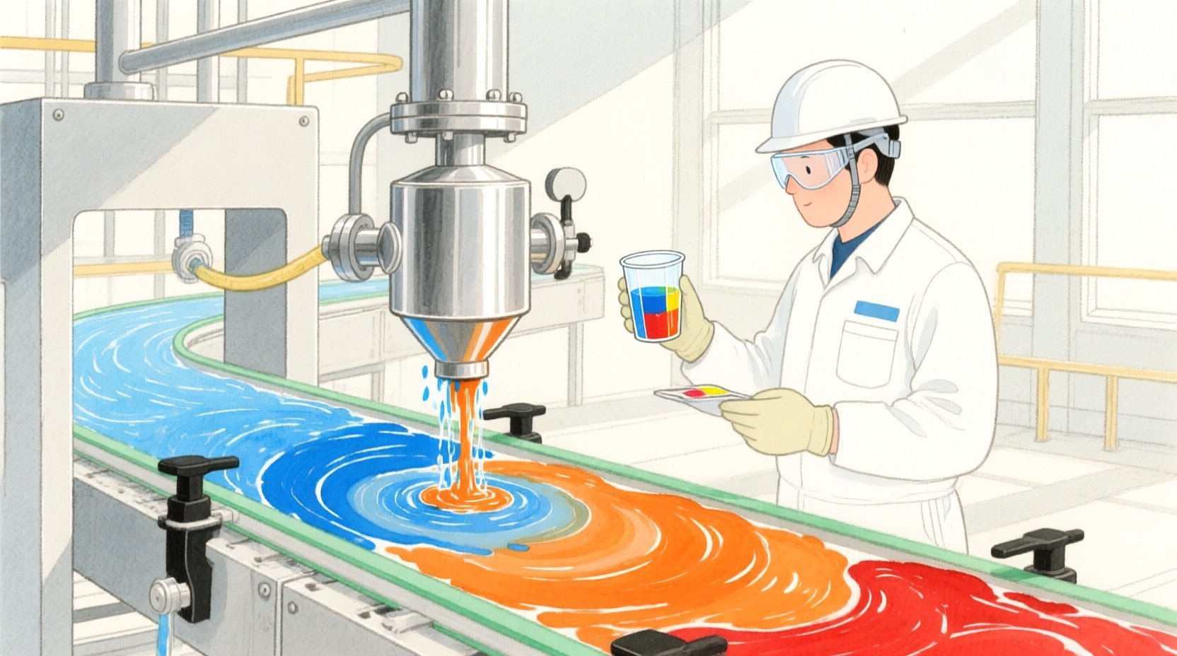
In modern automotive and industrial manufacturing, the paint coating line is a critical asset where precision and traceability are non-negotiable. Every time a production line switches from one color to another, a rigorous “flush sequence” must be executed to clean the supply path, pumps, and application bells. This process involves multiple steps using solvents, air, and purge cycles, each requiring detailed logging to prevent color cross-contamination. Simultaneously, viscosity measurements must be captured at specific checkpoints to ensure the coating material meets strict application specifications. Without a robust data model to link these events, operators and quality engineers struggle to audit defects or validate cleaning effectiveness.
Managing this complexity requires more than just spreadsheets; it demands a structured Entity Relationship Diagram (ERD) that clearly defines how changeover events, equipment, materials, and operators interact. By visualizing the relationships between flush steps, viscosity samples, and color specifications, teams can build a single source of truth for their manufacturing execution systems. This diagram serves as the architectural blueprint for databases that track the entire lifecycle of a color change, ensuring that every drop of paint and every minute of cleaning is accounted for.
Using diagram-as-code tools like VPasCode, architects can rapidly prototype and iterate on these data models. Instead of manually drawing boxes and lines in a GUI, writing the ERD in PlantUML allows for versionable, text-based documentation that evolves with the system. This approach ensures that the logical structure of your manufacturing data remains consistent, scalable, and easily understandable by both developers and domain experts.
Understanding the Model: Purpose, Scope & Problem Framing
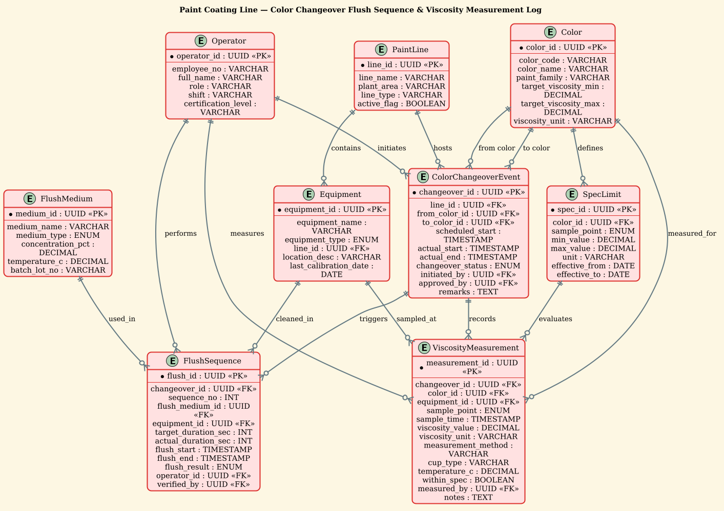
This diagram represents a specialized domain model for manufacturing quality control, specifically focusing on the operational data generated during a paint color changeover. The primary abstraction here is the Event-Driven Process: a color changeover event acts as the parent container for all subsequent actions, including the flush sequence and viscosity checks.
The scope of this model covers the entire data lifecycle of a changeover. It starts with the ColorChangeoverEvent, which triggers the FlushSequence (the cleaning process) and the ViscosityMeasurement (the quality check). The model explicitly links physical assets (Equipment, PaintLine) with process parameters (FlushMedium, SpecLimit) and human actors (Operators). This ensures that every data point is traceable to a specific location, a specific person, and a specific time.
Key takeaways from this model include the ability to trace defects back to a specific flush step, validate that viscosity readings fall within the SpecLimit defined for a color, and audit which operator performed which task. It solves the problem of fragmented data by creating a unified graph of relationships that supports complex queries for quality assurance and maintenance analytics.
Complete Diagram & Full Source Code
Below is the complete visual representation of the Paint Coating Line data model, followed by the full PlantUML source code. This ERD illustrates the cardinality of relationships, showing how one changeover event can trigger multiple flush steps and viscosity measurements.
@startuml
!theme sunlust
title Paint Coating Line — Color Changeover Flush Sequence & Viscosity Measurement Log

/'
Diagram Context:
This ERD models the operational records generated when a paint coating line switches
from one color to another. A color changeover event triggers a flush sequence that
cleans the paint supply path (pumps, lines, bells/cups, and valves) using solvents,
air, and purge cycles before the next color is introduced. Each flush step is logged
with sequence order, duration, medium, and target equipment to verify proper cleaning
and prevent color cross-contamination. Viscosity measurements are captured for the
incoming paint batch and at defined checkpoints (e.g., supply tank, gun drop, return
line) to ensure the coating meets application specifications such as Zahn cup or
Brookfield readings. The model links changeover events, flush steps, equipment,
materials, viscosity samples, and operators so quality and maintenance teams can
trace defects, validate cleaning effectiveness, and audit viscosity compliance.
'/

entity "ColorChangeoverEvent" as CCE {
  * changeover_id : UUID <<PK>>
  --
  line_id : UUID <<FK>>
  from_color_id : UUID <<FK>>
  to_color_id : UUID <<FK>>
  scheduled_start : TIMESTAMP
  actual_start : TIMESTAMP
  actual_end : TIMESTAMP
  changeover_status : ENUM
  initiated_by : UUID <<FK>>
  approved_by : UUID <<FK>>
  remarks : TEXT
}

entity "PaintLine" as LINE {
  * line_id : UUID <<PK>>
  --
  line_name : VARCHAR
  plant_area : VARCHAR
  line_type : VARCHAR
  active_flag : BOOLEAN
}

entity "Color" as COLOR {
  * color_id : UUID <<PK>>
  --
  color_code : VARCHAR
  color_name : VARCHAR
  paint_family : VARCHAR
  target_viscosity_min : DECIMAL
  target_viscosity_max : DECIMAL
  viscosity_unit : VARCHAR
}

entity "FlushSequence" as FLUSH {
  * flush_id : UUID <<PK>>
  --
  changeover_id : UUID <<FK>>
  sequence_no : INT
  flush_medium_id : UUID <<FK>>
  equipment_id : UUID <<FK>>
  target_duration_sec : INT
  actual_duration_sec : INT
  flush_start : TIMESTAMP
  flush_end : TIMESTAMP
  flush_result : ENUM
  operator_id : UUID <<FK>>
  verified_by : UUID <<FK>>
}

entity "FlushMedium" as MEDIUM {
  * medium_id : UUID <<PK>>
  --
  medium_name : VARCHAR
  medium_type : ENUM
  concentration_pct : DECIMAL
  temperature_c : DECIMAL
  batch_lot_no : VARCHAR
}

entity "Equipment" as EQUIP {
  * equipment_id : UUID <<PK>>
  --
  equipment_name : VARCHAR
  equipment_type : ENUM
  line_id : UUID <<FK>>
  location_desc : VARCHAR
  last_calibration_date : DATE
}

entity "ViscosityMeasurement" as VISC {
  * measurement_id : UUID <<PK>>
  --
  changeover_id : UUID <<FK>>
  color_id : UUID <<FK>>
  equipment_id : UUID <<FK>>
  sample_point : ENUM
  sample_time : TIMESTAMP
  viscosity_value : DECIMAL
  viscosity_unit : VARCHAR
  measurement_method : VARCHAR
  cup_type : VARCHAR
  temperature_c : DECIMAL
  within_spec : BOOLEAN
  measured_by : UUID <<FK>>
  notes : TEXT
}

entity "Operator" as OPER {
  * operator_id : UUID <<PK>>
  --
  employee_no : VARCHAR
  full_name : VARCHAR
  role : VARCHAR
  shift : VARCHAR
  certification_level : VARCHAR
}

entity "SpecLimit" as SPEC {
  * spec_id : UUID <<PK>>
  --
  color_id : UUID <<FK>>
  sample_point : ENUM
  min_value : DECIMAL
  max_value : DECIMAL
  unit : VARCHAR
  effective_from : DATE
  effective_to : DATE
}

CCE ||--o{ FLUSH : triggers
CCE ||--o{ VISC : records
LINE ||--o{ CCE : hosts
LINE ||--o{ EQUIP : contains
COLOR ||--o{ CCE : "from color"
COLOR ||--o{ CCE : "to color"
COLOR ||--o{ VISC : measured_for
COLOR ||--o{ SPEC : defines
MEDIUM ||--o{ FLUSH : used_in
EQUIP ||--o{ FLUSH : cleaned_in
EQUIP ||--o{ VISC : sampled_at
OPER ||--o{ FLUSH : performs
OPER ||--o{ VISC : measures
OPER ||--o{ CCE : initiates
SPEC ||--o{ VISC : evaluates

@endumlStep-by-Step Architectural Walkthrough
Phase 1: Canvas Configuration & Layout Directives
The first step in building this diagram is setting the stage with the correct theme and metadata. We begin by loading the sunlust theme, which provides a warm, professional color palette suitable for manufacturing dashboards. The title directive sets the context immediately, and the comment block (wrapped in /' and '/) provides a narrative summary of the diagram’s purpose, which is crucial for documentation without cluttering the visual output.
@startuml
!theme sunlust
title Paint Coating Line — Color Changeover Flush Sequence & Viscosity Measurement Log

/'
Diagram Context:
This ERD models the operational records...
'/
Phase 2: Declaring Core Entities, Actors, and Boundaries
Next, we define the core entities. In this manufacturing context, the ColorChangeoverEvent is the central anchor. It contains the primary key changeover_id and foreign keys linking to the PaintLine, the source Color, and the target Color. We also define the PaintLine, Color, and Operator entities to establish the static data that drives the process.
entity "ColorChangeoverEvent" as CCE {
* changeover_id : UUID <>
--
line_id : UUID <>
from_color_id : UUID < >
to_color_id : UUID < >
... (other attributes)
}
entity "Operator" as OPER {
* operator_id : UUID <>
--
full_name : VARCHAR
... (other attributes)
}
Phase 3: Mapping Data Flows & Key Interactions
The most critical part of this ERD is the FlushSequence and ViscosityMeasurement entities. These are child entities that depend on the ColorChangeoverEvent. The FlushSequence tracks the cleaning steps (medium, equipment, duration), while ViscosityMeasurement tracks the quality checks. We define their attributes to capture granular details like actual_duration_sec, viscosity_value, and within_spec.
entity "FlushSequence" as FLUSH {
* flush_id : UUID <>
--
changeover_id : UUID <>
sequence_no : INT
flush_medium_id : UUID < >
... (other attributes)
}
entity "ViscosityMeasurement" as VISC {
* measurement_id : UUID <>
--
changeover_id : UUID <>
... (other attributes)
}
Phase 4: Grouping, Annotations & Visual Polish
Finally, we establish the relationships using PlantUML’s cardinality syntax. The ||--o{ syntax indicates that one parent entity (like ColorChangeoverEvent) can be associated with zero or more child entities (like FlushSequence). This visualizes the one-to-many relationship essential for logging multiple flush steps and viscosity readings per changeover.
CCE ||--o{ FLUSH : triggers
CCE ||--o{ VISC : records
LINE ||--o{ EQUIP : contains
Syntax & Keyword Deep Dive
This diagram leverages several key PlantUML ERD features to create a robust data model:
entity: Defines a table or entity in the database schema. The syntaxentity "Name" as ABBRallows for a readable label and a short alias for relationship definitions.{ ... }Block: Used inside an entity definition to list attributes. Attributes are separated by newlines.*(Primary Key): Placed before the attribute name (e.g.,* changeover_id) to denote a Primary Key.<and> <Stereotypes: Explicitly labels attributes as Primary Keys or Foreign Keys for clarity in the generated diagram.> --Separator: Used within the entity block to visually separate the Primary Key from other attributes, improving readability.||--o{Relationship: Represents a “one-to-many” relationship. The||indicates “one and only one” on the parent side, ando{indicates “zero or many” on the child side.
Best Practices & Pitfalls to Avoid
- Consistent Naming Conventions: Use clear, descriptive names for entities (e.g.,
ColorChangeoverEventinstead ofEvent) and consistent abbreviations (e.g., always useCCEforColorChangeoverEvent) to keep the diagram clean. - Logical Grouping: Group related entities together in the code (e.g., all entities related to the flush process) to make the source code easier to navigate and maintain.
- Explicit Cardinality: Always define the cardinality explicitly. Ambiguous lines in an ERD can lead to database design errors, such as missing foreign key constraints.
- Avoid Over-Engineering: Start with the core entities needed for the specific workflow (like flush and viscosity) before adding general administrative tables, keeping the diagram focused on the problem at hand.
Start Building Manufacturing ERDs Faster with VPasCode
Instantly prototype your paint line data models, test relationship cardinalities, and export clean PlantUML code without installing any local tools.