


architecture-beta engine, this text-based tool replaces manual dragging utilities by auto-arranging structural service groups, database clusters, gateways, and edge paths into clean, predictable system layouts.
Basic Syntax Structure
Every diagram starts with thearchitecture-beta declaration header. You populate the canvas by defining individual node elements using the service keyword, and map connection tracks by specifying exact directional coordinate ports (Top, Bottom, Left, Right) separated by colons and double dashes.
Mermaid
Edit Mermaid in VPasCode
architecture-beta
  service gateway(internet)[Gateway Label]
  service server(server)[App Server]

  gateway:B -- T:server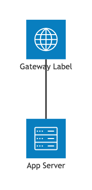
Syntax Reference
The table below breaks down the primary data components, formatting keywords, and connector attributes used to construct an architecture workspace map in Mermaid.js.| Syntax Component | Type Requirement | Description & Usage Rules |
|---|---|---|
| Declaration | Keyword Identifier | Initializes the infrastructure mapping workspace canvas. Must use the exact architecture-beta block. |
| Service Node | Keyword + Identity Block | Declares an architectural entity. Uses the syntax: service id(icon)[Display Label]. |
| Group Wrapper | Container Keyword | Groups related services inside a visual container. Uses the syntax: group id(icon)[Group Label]. |
| In Keyword | Assignment Modifier | Explicitly assigns a service node to reside inside a specific declared group wrapper: service id(icon)[Label] in groupId. |
| Junction Node | Keyword Identifier | Establishes a structural alignment hub point used to neatly route complex, multi-directional link paths: junction id. |
| Connection Edges | Port Direction Operators | Configures directional tracking paths by pinning the link to specific node sides (T, B, L, R): source:side -- side:target. Supports directional arrow tips (-->). |
Advanced Grouping & Port Edge Routing
To control exactly how links travel between elements without looking messy, the architecture engine requires explicit port bindings. Related nodes can be organized inside structural groups to clarify system boundaries.1. Exact Port Binding Rules
You define where a connection line leaves and enters a component by appending a colon and an edge direction flag (T, B, L, R) to the respective node identifiers:
db:R -- L:server: Line exits the **Right** of the database and enters the **Left** of the server as a straight horizontal line.db:T -- L:server: Line exits the **Top** of the database and enters the **Left** of the server, bending automatically at a clean 90° elbow angle.src:B --> T:proc: Line exits the **Bottom** of the source node and paths down into the **Top** of the processor with a directional arrow tip.
2. Structuring Systems with Groups
To declare a visual group (like a virtual private cloud or database cluster), use thegroup keyword, and assign nodes to it via the in modifier:
Mermaid
Edit Mermaid in VPasCode
architecture-beta
  group cloudNetwork(cloud)[Private Cloud]
    service auth(server)[Auth Node] in cloudNetwork
    service api(server)[API Endpoints] in cloudNetwork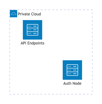
Aligning Sibling Elements (v11.16.0+)
When multiple distinct services share identical edge routing pathways (for example, three decoupled data sources streaming into a single message worker), the layout algorithm can sometimes bunch them together. Thealign row and align column directives force the engine to distribute those sibling elements evenly across a specific axis line.
Mermaid
Edit Mermaid in VPasCode
architecture-beta
  service src1(server)[Source 1]
  service src2(server)[Source 2]
  service proc(server)[Processor Hub]

  src1:B --> T:proc
  src2:B --> T:proc

  align row src1 src2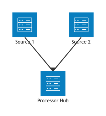
Real-World Blueprint: The Microservice Cluster Blueprint
This blueprint demonstrates a highly resilient, enterprise-grade cloud architecture. By centering the primary API engine and branching authentication and asynchronous tasks horizontally to its sides, the layout utilizes symmetric design principles to prevent overlapping lines. The entire data flow moves predictably down from the public gateway into a cleanly aligned data storage layer, utilizing dualalign row directives to lock components into sharp, predictable horizontal tracks.
Mermaid
Edit Mermaid in VPasCode
architecture-beta
  title "High-Availability Microservice Architecture"

  %% External Entry Tier
  service cloudflare(internet)[Cloudflare WAF]
  service alb(server)[AWS Application Load Balancer]

  %% Core Application Cluster
  group appCluster(cloud)[Managed EKS Microservices]
    service authService(server)[Auth Service] in appCluster
    service apiService(server)[Core API Engine] in appCluster
    service workerNode(server)[Async Task Worker] in appCluster

  %% Secured Storage Tier
  group dataCluster(database)[Protected Data Layer]
    service redis(disk)[Redis Cache Cluster] in dataCluster
    service postgres(database)[PostgreSQL Primary] in dataCluster

  %% 1. Vertical Flow: Traffic entry from public down to computing core
  cloudflare:B --> T:alb
  alb:B --> T:apiService

  %% 2. Horizontal Flow: Core API branching left and right symmetrically
  apiService:L --> R:authService
  apiService:R --> L:workerNode

  %% 3. Baseline Flow: App workers dropping down directly into respective data slots
  authService:B --> T:redis
  workerNode:B --> T:postgres

  %% Layout Axis Alignments for a Perfect Grid Grid
  align row authService apiService workerNode
  align row redis postgres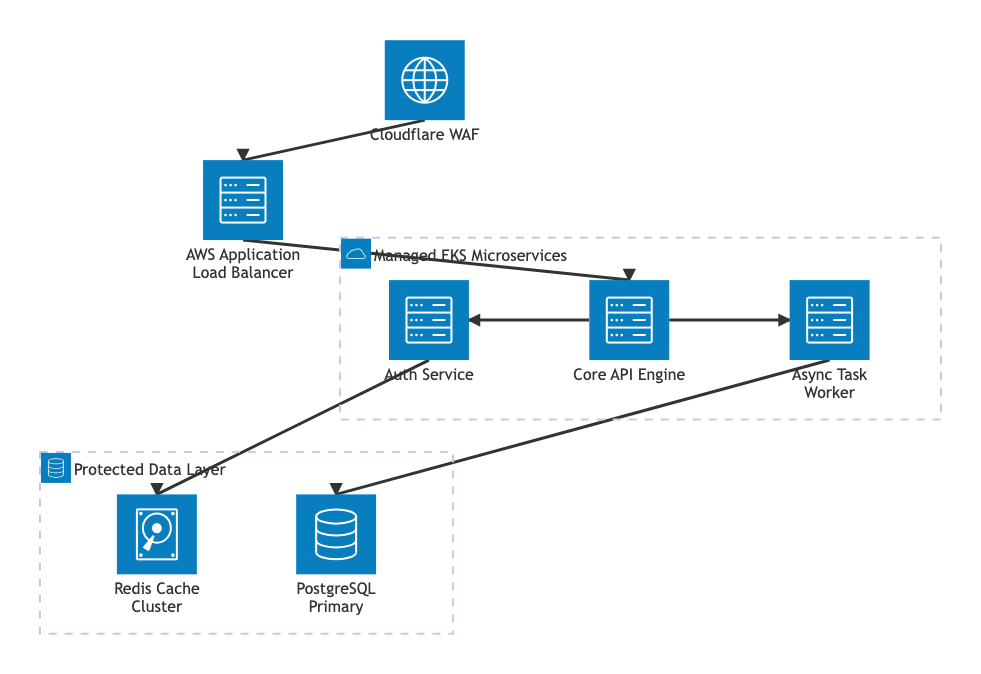
Common Syntax Pitfalls & System Constraints
When writing infrastructure code, keep these specific configuration validation rules in mind to prevent parsing faults:- Label Bracket Sequence: Display text strings must use square brackets
[Label Text]and follow the icon parentheses directly without spaces:service id(server)[Text]is correct. Using quotation marks inside the parenthesis will break the parser. - Port Case Sensitivity: Connection edge port anchors must be written in uppercase characters (
T,B,L,R). Lowercase letters (t,b,l,r) are unrecognized and will cause layout generation crashes. - Pre-Declaration Rule: Every node or junction identifier used inside an edge pathway statement must be explicitly declared on a separate line above it. Connecting to an implicit node name will fail to build.
- Align Member Limits: When using the
align roworalign columnpositioning directives, you must supply at least two or more valid, previously declared service or junction identifiers on the command line.