


What is an Activity Diagram?
An Activity Diagram is a behavioral UML diagram that functions as a high-powered, formalized flowchart for software applications. As a vital component of the Unified Modeling Language (UML) specification, it maps out the step-by-step operational workflow of a system component, business process, or algorithmic execution loop. By tracking the sequential flow of control from an initial starting point to a final conclusion, this specific UML diagram type helps software engineers, product managers, and business analysts chart complex system logic, identify edge cases, and visually isolate parallel execution paths before writing a single line of backend logic. With VPasCode, you don’t need to manually arrange flow boxes, calculate arrow intersections, or balance layout spacing. The engine uses a modernized, script-like formatting standard to instantly generate clean, highly readable layout vectors as you code.Core Syntax Guide: Elements and Constructs
To design an elegant, standards-compliant UML activity diagram in PlantUML, you need to master execution checkpoints, activity states, conditional branches, parallel splits, and vertical swimlanes.1. Execution Checkpoints and Basic Activities
Unlike legacy UML notations, modern activity scripts use clean, explicit command tags to mark the boundaries of your workflow. An activity node is defined simply by placing text inside a trailing colon and semicolon:
PlantUML
Edit PlantUML in VPasCode
start
:Initialize Application Context;
:Load Local Configuration Cache;
stop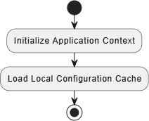
2. Conditional Logic Branches (if / else / switch)
To branch your control logic based on operational parameters, use standard programming syntax loops. You can append labels inside parenthesis to indicate the specific evaluation criteria required to pass down an arrow line:- Binary Forks (if / elseif / else): Ideal for simple true/false validation checks:
PlantUML Edit PlantUML in VPasCode
if (Is Token Valid?) then (yes)
    :Grant API Access;
else (no)
    :Redirect to Login;
endif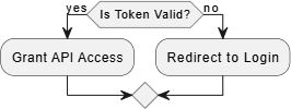
- Multi-Path Switches (switch): Perfect for evaluating numerical ranges, role tiers, or string matching patterns without nesting endless if statements:
PlantUML Edit PlantUML in VPasCode
switch (User Role Type)
case ( Admin )
    :Render Full Console;
case ( Moderator )
    :Render Control Panel;
case ( Guest )
    :Render Read-Only Feed;
endswitch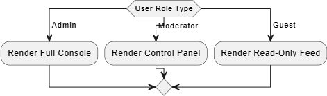
3. Parallel Executions (fork / join)
When modeling contemporary cloud environments or multi-threaded code loops, you often need to represent tasks that occur concurrently. Use thefork construct to split your execution string into independent, parallel lanes, and conclude with a join token to merge them back into a single thread:
PlantUML
Edit PlantUML in VPasCode
fork
    :Generate Email Invoice;
fork again
    :Deduct Warehouse Inventory;
end fork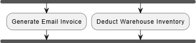
4. Organizing Responsibility with Swimlanes
To clearly define which actor, service team, or microservice infrastructure boundary owns a specific action, use vertical partitions known as swimlanes. You declare a swimlane by wrapping a title string inside pipe characters (|Lane Title|):
PlantUML
Edit PlantUML in VPasCode
|Client App|
start
:Click Purchase Button;
|#LightBlue Payment Gateway|
:Authorize Credit Card;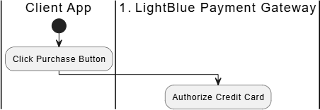
Best Practices for Clean Activity Flows
- Use Active Verb Labels: Keep your activity text blocks compact and clear by starting with action-oriented verbs (e.g.,
:Parse Payload;instead of:The payload data is parsed by the worker application;). - Color-Code High-Risk Nodes: Append custom hex colors directly onto sensitive background nodes (e.g.,
:#Crimson:Purge Database Records;) to make critical steps stand out visually in large enterprise maps. - Avoid Crossing Lines: If your multi-branch diagram begins to look cluttered, break up the text blocks by injecting a clean, circular connector node using the detach notation (
detach) or terminal anchors.
Real-World PlantUML Activity Diagram Examples
Example 1: User Onboarding and Identity Validation (Branches & Switches)
This boilerplate models a standard user onboarding workflow containing deep binary conditional logic and an identity verification check inside a clean UML diagram layout.
PlantUML
Edit PlantUML in VPasCode
@startuml
start
:User Submits Sign-Up Form;
if (Email Already Exists?) then (yes)
    :Show Account Conflict Warning;
    stop
else (no)
    :Create Pending User Record;
endif

:Send Verification OTP Code;
repeat
    :Await User OTP Input;
backward:Log Failed Attempt Alert;
repeat while (Is OTP Correct?) is (no) not (yes)

switch (Account Selection Tier)
case ( Premium Paid )
    :Provision Database Clusters;
    :Trigger Stripe Subscription Loop;
case ( Free Tier )
    :Apply Basic API Rate Limits;
endswitch

:Mark User Profile as Verified;
stop
@enduml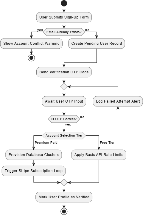
repeat / backward / repeat while validation loop that continuously captures user entries until the correct security key is passed. The multi-path switch wrapper neatly segregates account setup logic based on tier status values.
Example 2: Distributed Order Fullfillment Engine (Swimlanes & Parallel Forks)
This complex enterprise architecture map leverages structural vertical swimlanes to trace exactly how an automated checkout flow processes tasks concurrently across a browser client, an API gateway, and a physical fulfillment center.
PlantUML
Edit PlantUML in VPasCode
@startuml
|#White|Client Application|
start
:Submit Shopping Cart;
:Select Shipping Address;

|#LightCyan|Checkout API Engine|
:Validate Product Inventory;
if (Items In Stock?) then (no)
    :Return Out Of Stock Error;
    stop
else (yes)
    :Lock Inventory Allocations;
endif

fork
    :Process Payment via Stripe;
    :Generate Digital PDF Receipt;
fork again
    |#Lavender|Warehouse Management System|
    :Print physical Packing Slip;
    :Assign Warehouse Robot Picker;
end fork

|#LightCyan|Checkout API Engine|
:Dispatch Order Confirmation Hook;
stop
@enduml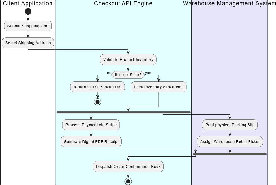
|#Lavender Warehouse Management System|) forces the automated layout engine to build crisp, separate columns. The parallel fork statement clearly shows that payment processing on the API engine and packing slip generation in the physical warehouse happen concurrently, merging back cleanly before the terminal stop block.