


What is a Sequence Diagram?
A Sequence Diagram is a behavioral UML diagram that details how software operations are carried out over time. As a core standard of the Unified Modeling Language (UML) specification, it models the precise chronological order in which objects, processes, or microservices exchange messages. By mapping lifelines vertically and sequential interactions horizontally, this specific UML diagram type allows software engineers and system architects to clearly visualize complex API call sequences, network data handshakes, and database transaction boundaries before writing production code. With VPasCode, you don’t have to spend hours aligning parallel arrows, stretching message lines, or shifting bounding boxes around to make space for a new step. Our layout engine computes the entire timeline grid dynamically as you type your plain-text declarative scripts.Core Syntax Guide: Elements and Constructs
To design an actionable, standards-compliant UML sequence diagram in PlantUML, you need to master component declarations, message arrow styles, lifelines, and logical control structures.1. Declaring UML Participants and Shapes
By default, components in this UML diagram inherit a standard square box shape. However, you can change the visual archetype of your entities to give readers instant architectural context about your system boundaries using specific UML keywords:
PlantUML
Edit PlantUML in VPasCode
actor Client
boundary "API Gateway" as Gateway
control Controller
database "PostgreSQL" as DB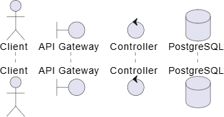
2. Message Arrows and Synchronicity
The style of your arrow lines and heads establishes the exact communication protocol occurring across your infrastructure pipelines based on UML diagram standards:- Synchronous Request (Blocking): Indicated by a solid line and a solid arrow head. The sender waits for a response:
A -> B - Asynchronous Message (Non-Blocking): Indicated by a solid line and an open thin arrow head. The sender passes data and proceeds immediately:
A ->> B - Response / Return Value: Indicated by a dotted line and an open arrow head:
B --> A
3. Managing Lifelines (Activation and Deactivation)
To prevent your components from looking like flat bars, you should explicitly show when a process is actively consuming CPU threads or memory capacity. Use theactivate and deactivate markers, or use the shorthand inline increment syntax (++ / --):
PlantUML
Edit PlantUML in VPasCode
Gateway -> Controller ++ : "processPayment()"
Controller --> Gateway -- : "return receipt"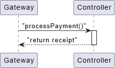
4. Logic Blocks: Alternatives, Loops, and Parallels
Complex business logic (such as if/else forks, database retries, or parallel execution threads) must be wrapped inside structured global frame boundaries known as combined fragments in the UML diagram specification:- Conditional Logic (alt / else): Models conditional forks.
PlantUML Edit PlantUML in VPasCode
alt successful condition
    A -> B : "Proceed with request"
else failure state
    A -> B : "Throw error code"
end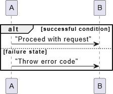
- Repetition Loops (loop): Models iterations, retries, or queue processing blocks until a condition is satisfied.
PlantUML Edit PlantUML in VPasCode
loop until queue is empty
    Worker -> Queue : "Fetch next job"
end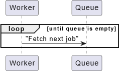
- Parallel Executions (par): Models separate operations executing simultaneously across independent threads.
PlantUML Edit PlantUML in VPasCode
par Run parallel processes
    A -> LogService : "Write trace analytics"
else
    A -> DB : "Commit customer profile data"
end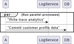
Best Practices for Clean Sequences
- Group Messages Using Dividers: Use double equal signs (
== Your Phase ==) to break a massive authentication-to-checkout sequence into distinct logical milestones. - Utilize Autonumbering: Place the
autonumberdirective directly below@startuml. This forces the workspace to stamp step integers on every arrow, making code reviews significantly easier. - Keep Responses Clean: Avoid writing huge descriptive sentences on return arrows (
-->). Instead, simply label what raw data object or HTTP code is traveling back (e.g.,"201 Created Token").
Real-World PlantUML Sequence Diagram Examples
Example 1: Microservice Authentication Loop (Alt Blocks & Lifelines)
This boilerplate handles a standard security sequence where a client authenticates against a gateway, showcasing explicit lifelines and an alternate conditional outcome framework inside a standard UML diagram format.
PlantUML
Edit PlantUML in VPasCode
@startuml
autonumber
actor User
boundary "Web App" as App
control "Auth Service" as Auth

User -> App ++ : "Submit Credentials"
App -> Auth ++ : "POST /v1/auth"

alt #LightGreen Successful Login
    Auth --> App : "200 OK (JWT Token)"
    App --> User : "Render Dashboard"
else #LightPink Invalid Credentials
    Auth --> App : "401 Unauthorized"
    App --> User : "Show Error Toast"
end

deactivate Auth
deactivate App
@enduml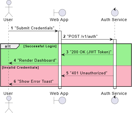
autonumber tag automatically manages numbers 1 through 5. The alt and else blocks are appended with custom hex color flags (e.g., #LightGreen) to add an immediate visual highlight to success vs. failure execution paths. The ++ tokens ensure the lifelines remain active during the network call block.
Example 2: Advanced Order Processing (Loops, Parallels, and Dividers)
This enterprise architecture blueprint models a robust checkout system that splits tasks across parallel workers, executes database writes, and relies on an external system sync loop.
PlantUML
Edit PlantUML in VPasCode
@startuml
autonumber
boundary "Checkout API" as API
database "Orders DB" as DB
control "Worker Queue" as Queue
boundary "Stripe" as Stripe

== Phase 1: Transaction Ledger Validation ==
API -> DB ++ : "Write Pending Order"
DB --> API -- : "Order ID Confirmed"

== Phase 2: Payment & Async Fulfillment ==
API -> Stripe ++ : "Charge Customer Account"
Stripe --> API -- : "Payment Authorized"

par Parallel Background Operations
    API -> Queue ++ : "Publish 'Order_Placed' event"
    deactivate Queue
else
    API -> DB ++ : "Update status to 'Paid'"
    deactivate DB
end

loop Retrying Up To 3 Times on Network Failure
    API -> API : "Ping Notification Sync Webhook"
end

API --> Client : "Return HTTP 200 (Success)"
@enduml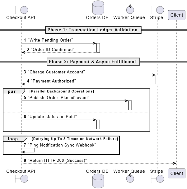
== dividers split the layout into distinct operational phases. The par block cleanly branches off the messaging arrow path into two separate horizontal paths, illustrating that event publication and database status updates occur simultaneously without blocking each other. The self-pointing arrow (API -> API) maps a local internal instance function loop perfectly.