


What is a Timing Diagram?
A Timing Diagram is a specialized behavioral UML diagram designed to visualize the exact duration of states and the precise conditions under which those states change along a linear timeline. As an essential part of the Unified Modeling Language (UML) specification, this specific UML diagram type focuses heavily on hard time constraints, clock cycles, and wave signals. It tracks waveforms or step-lines to illustrate exactly how long an object remains in a specific condition before an external trigger shifts its state. Timing maps are widely used by embedded systems engineers, network protocol developers, and hardware architects to model race conditions, track thread lifecycle changes, or map hardware register transitions. With VPasCode, you don’t have to manually calculate pixel widths or map timeline coordinates. Our rendering engine handles the entire temporal grid automatically based on your plain-text scripts.Core Syntax Guide: Elements and Constructs
To design an accurate, standards-compliant UML timing diagram in PlantUML, you need to master participant types, state definitions, time intervals, and synchronization constraints.1. Declaring Participants (Robust vs. Concise)
You can model timelines using two distinct visual styles depending on how much detail your system requires. You must declare them using explicit keywords:- Robust Timelines: Displays states as distinct, stacked rows. Ideal for high-level software processes.
robust "Application Thread" as Thread - Concise Timelines: Displays states along a single flat line, using cross-hatched blocks to indicate changes. Perfect for compact hardware signal maps.
concise "CPU Register" as Reg
2. Defining State Transitions and Time Steps
Unlike other diagrams, you change states by declaring a time checkpoint using the@ symbol, referencing your participant, and using the is keyword. State names containing spaces or special characters must be wrapped in quotation marks:
@0
Thread is Idle

@10
Thread is "Processing Data"
3. Generating Clock Signals
To simulate binary hardware clocks, use theclock keyword. You must specify a cycle period, an optional duty cycle, and an internal name:
clock "System Clock" as CLK with period 24. Adding Precision Constraints and Time Slates
To document strict execution deadlines (such as ensuring a system transition happens within a specified window), use the<-> syntax to bridge two time coordinates with a descriptive label:
@10 <-> @40 : {Less than 30ms}Best Practices for Clean Timing Layouts
- Keep Time Units Uniform: PlantUML treats timeline integers as generic sequential steps. Choose a uniform time unit for your project (e.g., ticks, microseconds, or seconds) and maintain it consistently.
- Use Labels for Intricate Transitions: You can append text messages directly onto state changes by adding a colon immediately after the state assignment (e.g.,
@10\nReg is Reading : "Trigger Interrupt"). - Order Declarations Strategically: PlantUML stacks lifelines vertically in the exact order they are declared in your script. Always put your master clocks at the very top for easier alignment.
Real-World PlantUML Timing Diagram Examples
Example 1: Microcontroller Cache & Register States (Concise & Clock Waveforms)
This runnable blueprint demonstrates a classic embedded hardware engineering timeline, running a standard system clock alongside a concise data storage register tracking hardware states.
PlantUML
Edit PlantUML in VPasCode
@startuml
clock "System Clock (CLK)" as clk with period 2
concise "Data Bus Register" as Reg

@0
Reg is Empty

@2
Reg is Reading : "Fetch"

@6
Reg is Writing

@10
Reg is Locked

@14
Reg is Empty
@enduml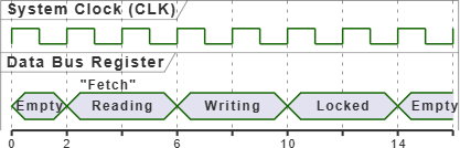
clock directive creates a rhythmic high/low square wave automatically. The Reg line handles multiple state assignments sequentially over the absolute timeline grid. Text strings appended with a colon (like : "Fetch") render as neat callouts directly over the transition boundary line.
Example 2: Async Web Consumer Token Refresh (Robust Multi-Thread Constraints)
This advanced, fully functional software architecture blueprint leverages the robust layout format to trace a multi-threaded web application workflow, mapping precise timing deadlines between a web client and an authorization worker.
PlantUML
Edit PlantUML in VPasCode
@startuml
robust "Web Browser Client" as Web
robust "Auth Token Worker" as Auth

@0
Web is Idle
Auth is Sleep

@5
Web is AwaitingToken
Auth is Validating

@15
Auth is Generating

@15 <-> @25 : {Generation Window}

@25
Auth is Sleep
Web is RenderingPage

@40
Web is Idle
@enduml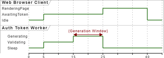
robust declaration, the states are cleanly listed on the Y-axis for each individual lifeline row. The time evaluation constraint (@15 <-> @25 : {Generation Window}) draws a standard double-sided dimension arrow across the top of the timeline grid, indicating a strict operational limit.