


What is a State Diagram?
A State Diagram (also known as a Statechart) is a behavioral UML diagram that models the finite lifecycle of a single object or subsystem. Recognized as a core UML diagram type, it illustrates the discrete conditions (states) an entity can occupy, the external events or triggers that force a shift between those conditions (transitions), and the conditional rule forks that alter execution pathways. This mapping is essential for tracking complex object lifecycles, such as an order’s progression from fulfillment to delivery, a user session timeout sequence, or an embedded hardware switch loop. With Mermaid.js, you can define your reactive state machines using a declarative, text-driven schema. The parsing engine automatically calculates optimal layout spacing, handles recursive looping arrows, and scales state container boundaries smoothly.Core Syntax Guide: Elements and Constructs
To design an accurate, standards-compliant UML state diagram in Mermaid, you must master entry/exit markers, transition strings, composite nesting, and conditional choice blocks.1. Defining Entry, Exit, and Standard States
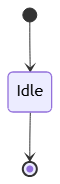
You initialize a state canvas on line one using thestateDiagram-v2 keyword. Lifecycles require explicit starting and stopping points, which are represented by a solid circle symbol ([*]):
- Initial State (Entry):
[*] --> StateName(Marks where the lifecycle starts). - Terminal State (Exit):
StateName --> [*](Marks where the lifecycle concludes).
2. Configuring Transition Triggers and Event Labels
To map a state change, connect your defined state tokens using a standard arrow line (-->). To document the exact event, API response, or button click that causes this transition, append a colon (:) followed by your descriptive text string:
Mermaid
Edit Mermaid in VPasCode
stateDiagram-v2
    Active --> Suspended : PaymentFailed
    Suspended --> Active : InvoiceSettled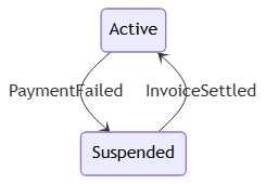
3. Implementing Conditional Choice Blocks
To handle branching evaluation loops, use the<<choice>> stereotype. This creates a clear diamond shape on the canvas that splits a single inbound transition path into multiple distinct outbound paths based on runtime logic checks:
Mermaid
Edit Mermaid in VPasCode
stateDiagram-v2
    state check_status <<choice>>
    [*] --> check_status
    check_status --> PremiumUser : if balance >= 100
    check_status --> StandardUser : if balance < 100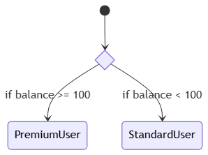
4. Structuring Composite (Nested) States
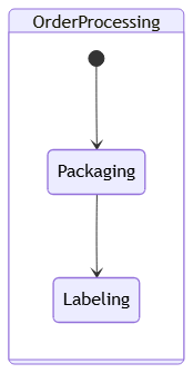
When modeling a complex system, a single high-level state can contain its own independent inner lifecycle. You can create a nested sub-state layout by defining a parent state followed by a body block wrapped in curly braces:
Mermaid
Edit Mermaid in VPasCode
stateDiagram-v2
    state OrderProcessing {
        [*] --> Packaging
        Packaging --> Labeling
    }
Best Practices for Clean State Machine Layouts
- Keep State Tokens Short: Use brief CamelCase text strings for your internal state tokens (e.g.,
AwaitingRefund). If you need a long descriptive title on the canvas, use thestate "Descriptive Text Block" as Tokensyntax to create an explicit alias. - Enforce a Single Entry Point: Always start your diagram from a single
[*]node. Having multiple starting points can confuse users trying to track the root initialization path of the system. - Always Use stateDiagram-v2: Always choose the
stateDiagram-v2keyword over the legacystateDiagramflag. The v2 rendering engine uses an updated layout algorithm that provides cleaner line routing and better nested box alignments.
Real-World Mermaid.js State Diagram Examples
Example 1: Digital Wallet Transaction Lifecycle (Choice Branches & Failure Loops)
This functional blueprint models the lifecycle of a digital payment transaction, showing how a transaction moves from an initial submission point through a fraud check fork into finalized ledger states.
Mermaid
Edit Mermaid in VPasCode
stateDiagram-v2
    state fraud_check <<choice>>

    [*] --> TransSubmitted
    TransSubmitted --> fraud_check : ExecuteRiskAssessment

    fraud_check --> TransApproved : Risk Score Low
    fraud_check --> TransFlagged : Risk Score Elevated

    TransFlagged --> TransApproved : ManualManagerOverride
    TransFlagged --> TransDeclined : SecurityTimeout

    TransApproved --> SettlementPending : CommitLedger
    SettlementPending --> TransCompleted : BankSettlementSuccess

    TransDeclined --> [*]
    TransCompleted --> [*]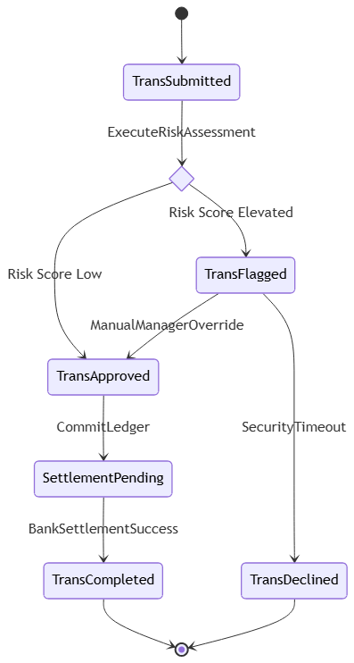
<<choice>> block to evaluate safety scores right at the start. The transaction transitions along distinct pathways based on these scores, with clear event names (like ExecuteRiskAssessment) documented directly on the transition arrows.
Example 2: E-Commerce Order Fulfillment Pipeline (Composite Nested Systems)
This advanced enterprise blueprint outlines a complete shipping and order management lifecycle, using nested composite blocks to show the internal operations happening within the fulfillment phase.
Mermaid
Edit Mermaid in VPasCode
stateDiagram-v2
    [*] --> OrderPlaced

    OrderPlaced --> InFulfillment : PaymentCaptured

    state InFulfillment {
        [*] --> ItemPicking
        ItemPicking --> QualityAudit : BatchPicked
        QualityAudit --> SecureBoxPacking : AuditPassed
        SecureBoxPacking --> CarrierManifest Generated : LabelPrinted
    }

    InFulfillment --> Shipped : CarrierHandshake
    Shipped --> Delivered : OutForDeliveryConfirmed

    Delivered --> [*]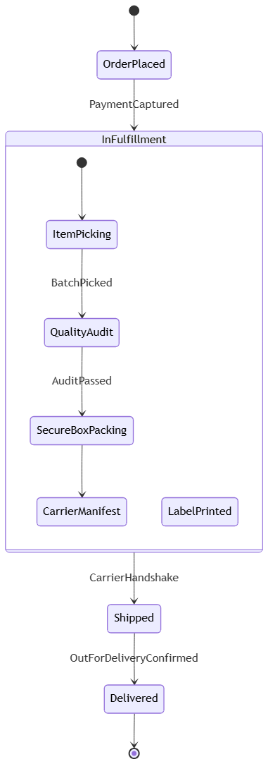
state InFulfillment {...} body block, you create a clear structural boundary on the canvas. The engine treats this block as a single consolidated parent state while rendering its internal workflow steps sequentially, making complex multi-layered lifecycles easy to navigate.