


What is a State Diagram?
A State Diagram (often called a State Machine or Statechart Diagram) is a behavioral UML diagram that models the lifecycle of a single system object, business entity, or runtime process. As a fundamental component of the Unified Modeling Language (UML) specification, this specific UML diagram type illustrates the various states an object can inhabit from its initial instantiation to its final destruction, along with the specific events or conditions that trigger a change from one state to another. Whether you are documenting the intricate connection flags of a WebSocket connection, the order processing steps of an e-commerce checkout model, or the behavior of an autonomous hardware system, a UML state machine provides software developers and software architects with a clear, unambiguous blueprint of complex reactive logic. With VPasCode, you can script out complex state transitions instantly without wrestling with grid alignments or overlapping boundary arrows.Core Syntax Guide: Elements and Constructs
To write high-quality, standard-compliant statechart layouts, you need to understand start and end points, state definitions, event transitions, nested composite states, and conditional choice points.1. Initial and End States
Every state machine must have an entry point and, optionally, a terminal point. In PlantUML syntax, these boundary elements are represented by a clean asterisk symbol wrapper:[*] --> StateName(Defines the initial start state)StateName --> [*](Defines the terminal end state)
2. Defining States and Event Transitions
States are declared automatically whenever they are linked by a directional arrow (-->). To add context to a transition, append a colon (:) followed by the specific event, API trigger, or method call that causes the state change:
PlantUML
Edit PlantUML in VPasCode
[*] --> Disconnected
Disconnected --> Connecting : "connect()"
Connecting --> Connected : "auth_success"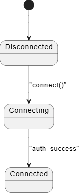
3. Composite / Nested States
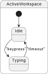
Complex applications often feature individual states that contain their own nested sub-states. You can implement these composite structures by using thestate keyword followed by an opening curly brace:
PlantUML
Edit PlantUML in VPasCode
state ActiveWorkspace {
    [*] --> Idle
    Idle --> Typing : "keypress"
    Typing --> Idle : "timeout"
}
4. Choice Points (Conditional Branching)
When an event occurs, the system often has to evaluate internal data flags before determining the next state destination. To draw a standard UML choice diamond, use the<<choice>> stereotype token:
PlantUML
Edit PlantUML in VPasCode
state check_payment <<choice>>
OrderPlaced --> check_payment : "process()"
check_payment --> Paid : [balance >= total]
check_payment --> Failed : [balance < total]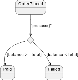
Best Practices for Clean Statecharts
- Leverage State Descriptions: You can append clear operational details, entry hooks, or exit functions straight inside a state node by using a colon wrapper inline (e.g.,
StateName : entry / logTimestamp()). - Keep State Names Compact: Use CamelCase or snake_case for your internal state variable codes (e.g.,
PaymentProcessing), and use quotation marks if you need to attach a long human-readable label to them. - Manage Vector Routing directions: If your multi-tier lifecycle maps become cluttered vertically, inject inline spatial rules inside the connection arrows (e.g.,
-right->or-down->) to balance layout density.
Real-World PlantUML State Diagram Examples
Example 1: IoT Device Network Lifecycle (Composite States & Choices)
This boilerplate tracks the connection behavioral state loops of an IoT sensor module, demonstrating complex structural nested blocks and conditional evaluation choice pins.
PlantUML
Edit PlantUML in VPasCode
@startuml
[*] --> Offline

Offline --> Connecting : "power_on"

state Connecting {
    [*] --> Initializing
    Initializing --> ResolvingDNS : "hardware_ready"
    ResolvingDNS --> SendingHandshake : "ip_acquired"
}

state authentication_check <<choice>>
Connecting --> authentication_check : "receive_server_challenge"

authentication_check --> Online : [token_valid]
authentication_check --> Offline : [token_expired] : "blink_red_led"

state Online {
    [*] --> Idle
    Idle --> TransmittingData : "timer_trigger"
    TransmittingData --> Idle : "ack_received"
    Idle --> PowerSaving : "low_battery_detected"
}

Online --> Offline : "connection_lost"
@enduml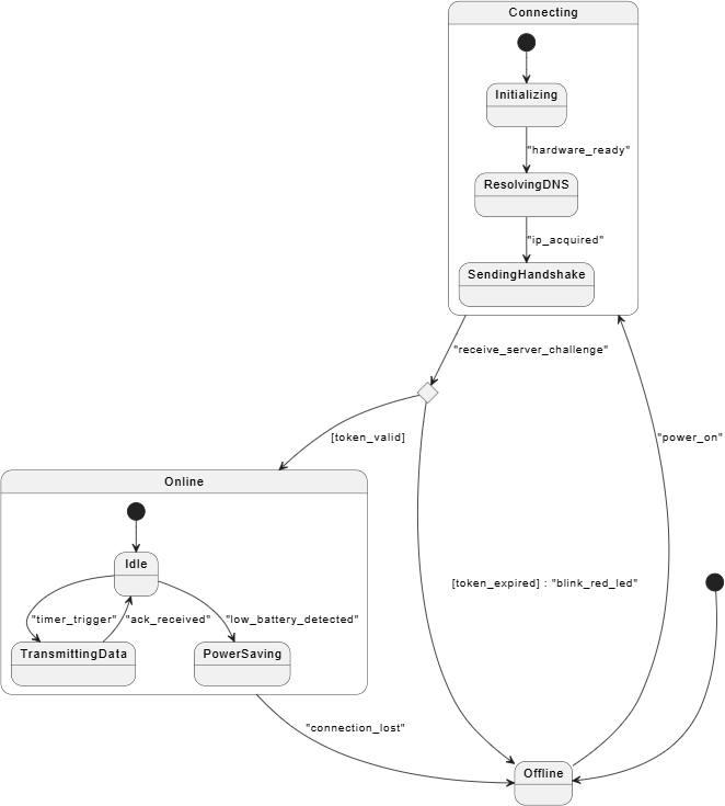
Connecting wrapper state, it tracks localized sub-states like DNS resolution before reaching the authentication_check choice diamond. The brackets ([token_valid]) represent standard UML guard conditions.
Example 2: E-Commerce Order Fulfillment State Machine (Concurrent Sub-States)
This advanced enterprise blueprint models a multi-threaded order system showing orthogonal concurrent behaviors (processing shipping packages and billing records simultaneously) using split lines (--).
PlantUML
Edit PlantUML in VPasCode
@startuml
[*] --> ShoppingCart

ShoppingCart --> OrderSubmitted : "checkout_click"
OrderSubmitted --> ProcessingPayment : "authorize_funds"

state ProcessingPayment {
    [*] --> ContactingBank
    ContactingBank --> SettlementSettled : "capture_success"
}

ProcessingPayment --> OrderConfirmed : "payment_cleared"

state OrderConfirmed {
    [*] --> LogisticsHandling
    state LogisticsHandling {
        [*] --> PickingItems
        PickingItems --> PackingBox : "inventory_secured"
        PackingBox --> OutForDelivery : "label_printed"
    }
    --
    [*] --> BillingRecords
    state BillingRecords {
        [*] --> CompilingInvoice
        CompilingInvoice --> InvoiceEmailed : "pdf_generated"
    }
}

OrderConfirmed --> OrderArchived : "delivery_confirmed"
OrderArchived --> [*]
@enduml
OrderConfirmed composite structure, the double dash delimiter (--) acts as an orthogonal divider. This instructs PlantUML to split the diagram into two concurrent states that execute in parallel: the physical logistics pipeline on the left, and the corporate billing updates on the right.