


What is an Entity Relationship Diagram (ERD)?
An Entity Relationship Diagram (ERD) is a structural blueprint used to design, document, and analyze relational database schemas. It outlines the specific data tables (entities) within an application, the columns (attributes) nested inside those tables, and the referential integrity rules that bind them together. Written using standard Information Engineering (IE) notation, it implements clear crow’s foot notation heads to show data constraints and multi-table dependencies. With Mermaid.js, you can define your production table indexes, data types, and foreign key connections using a clean, declarative text block. The engine automatically handles sizing for multi-column layout containers and routes connection lines without letting text labels overlap.Core Syntax Guide: Elements and Constructs
Building a valid, fully runnable database schema in Mermaid relies on structural entity blocks, data type mappings, index tags, and cardinality operators.1. Declaring Entities and Table Columns
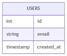
You initialize an ERD canvas on line one using theerDiagram keyword. To define a table, write the entity name followed by an open curly brace, listing your column configurations sequentially on individual lines:
Mermaid
Edit Mermaid in VPasCode
erDiagram
    USERS {
        int id
        string email
        timestamp created_at
    }
2. Marking Primary Keys, Foreign Keys, and Comments
Mermaid’s ERD engine allows you to assign structural indexing tags directly after the column name and data type definition. You can also append an optional text comment to a column by wrapping it in double quotes:PK— Explicitly flags a column as the table’s Primary Key.FK— Flags a column as a Foreign Key linked to a parent table.
Mermaid
Edit Mermaid in VPasCode
erDiagram
    ORDERS {
        int id PK
        int user_id FK "Links to USERS.id"
        string coupon_code
    }
3. Mastering Crow’s Foot Cardinality Modifiers
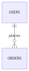
To connect tables and enforce referential integrity rules, map their relationships using specialized line operators. The character heads form visual crow’s foot shapes that dictate data multiplicity constraints:||--||**Exactly One to Exactly One:** A strict, mandatory 1:1 mapping.||--o|**Exactly One to Zero or One:** An optional 1:1 dependency.||--|{**Exactly One to One or Many:** A mandatory 1:N parental linkage.||--o{**Exactly One to Zero, One, or Many:** A standard, optional 1:N relationship.
Best Practices for Relational Data Schemas
- Maintain Consistent Table Casing: Keep entity names predictable. Use uppercase strings (e.g.,
USER_ACCOUNTS) or strict lowercase snake_case (e.g.,user_accounts) to match your real-world SQL infrastructure code. - Always Include Data Types: Avoid declaring raw column text without types. Explicitly listing definitions like
int,varchar, orbooleanensures your architecture charts serve as an accurate technical reference. - Keep Relationship Labels Verbs: When linking elements, provide a brief, lowercase active verb string inside your relationship assignment (e.g.,
||--o{ : "contains") to document the business logic mapping.
Real-World Mermaid.js ERD Examples
Example 1: Core E-Commerce Transactional Model (Keys & Mappings)
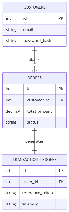
This functional blueprint models a core e-commerce database transaction loop, showing how users, orders, and payment tracking systems link together using strict crow’s foot constraints.
Mermaid
Edit Mermaid in VPasCode
erDiagram
    CUSTOMERS {
        int id PK
        string email
        string password_hash
    }

    ORDERS {
        int id PK
        int customer_id FK
        decimal total_amount
        string status
    }

    TRANSACTION_LEDGERS {
        int id PK
        int order_id FK
        string reference_token
        string gateway
    }

    CUSTOMERS ||--o{ ORDERS : "places"
    ORDERS ||--|| TRANSACTION_LEDGERS : "generates"
||--o{), while an individual order record must generate exactly one matching transaction ledger entry (||--||).
Example 2: Enterprise Content Management System Schema (Many-to-Many Intersection)
This advanced database blueprint maps out a content management platform architecture. It details how to resolve complex many-to-many configurations by introducing an explicit bridge mapping entity.
Mermaid
Edit Mermaid in VPasCode
erDiagram
    POSTS {
        int id PK
        string title
        string slug
        text body_content
    }

    CATEGORIES {
        int id PK
        string name
        string description
    }

    POST_CATEGORY_MAPPINGS {
        int post_id PK, FK
        int category_id PK, FK
        timestamp assigned_at
    }

    COMMENTS {
        int id PK
        int post_id FK
        string author_name
        text comment_body
    }

    POSTS ||--o{ POST_CATEGORY_MAPPINGS : "contains"
    CATEGORIES ||--o{ POST_CATEGORY_MAPPINGS : "classifies"
POSTS ||--o{ COMMENTS : "attaches" 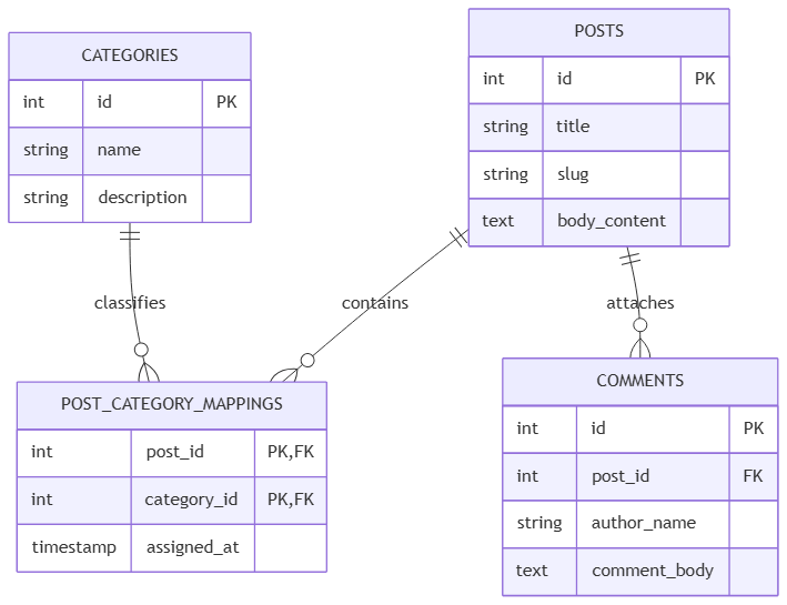
PK FK), linking the outer nodes together using standard one-to-many crow’s foot connections.