


What is a Flowchart?
A Flowchart is a foundational behavioral map that visualizes a step-by-step operational workflow, algorithmic procedure, or sequential business logic. By representing system actions as distinct geometric shapes and charting the control flow with directional arrows, a flowchart makes it easy for software engineers and systems architects to trace conditional execution paths, isolate single-point-of-failure blocks, and analyze system logic loops before writing actual backend code. With Mermaid.js, you don’t have to spend hours dragging boxes, micro-managing grid lines, or recalculating padding variables. The layout engine computes node coordinates dynamically from your raw declarative scripts, letting you focus entirely on your system’s underlying logic.Core Syntax Guide: Elements and Constructs
To design an elegant, highly scannable flowchart in Mermaid, you must master canvas direction indicators, geometric node enclosures, link wiring variables, and structural subgraphs.1. Setting Canvas Directions
The orientation of your flowchart is determined directly on line one by the keyword pairing applied to thegraph or flowchart wrapper. You can control the visual scaling direction of your layout using four primary orientation keys:
flowchart TD(Top to Down / Vertical orientation)flowchart BU(Bottom to Up orientation)flowchart LR(Left to Right / Horizontal orientation)flowchart RL(Right to Left orientation)
2. Customizing Node Geometry (Shapes)
By default, a plain ID declaration renders as a sharp rectangular box. To make your diagrams easier to scan, use Mermaid’s specialized enclosing brackets to inject instant visual context into different workflow steps. Every single definition block must be preceded by a directional layout token to parse correctly:- Round Edges:
id(Text)— Represents a general process step. - Stadium/Capsule Shape:
id([Text])— Standard marker for start and stop boundary milestones. - Subroutine/Predefined Process:
id[[Text]]— Represents an encapsulated system routine or external class script. - Cylinder/Database:
id[(Text)]— Represents database persistence, caches, or data warehouses. - Rhombus/Decision Diamond:
id{Text}— Represents conditional switches, if/else forks, or evaluation points. - Parallelogram:
id[/Text/]orid[\Text\]— Renders skewed boundaries to represent explicit data Input/Output (I/O).
Mermaid
Edit Mermaid in VPasCode
flowchart TD
    start_node([Start Execution])
    query_db[(PostgreSQL Instance)]
    validate_check{Is Authorized?}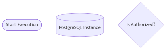
3. Link Wiring Rules and Inlined Labels
You can adjust your connector lines to represent different structural relationships and communication styles. To keep your charts clean, inject descriptive labels directly onto your link paths:
Mermaid
Edit Mermaid in VPasCode
flowchart TD
    %% Standard connector arrow with text label
    A --> |"JSON Payload"| B

    %% Dotted/Asynchronous line with text label
    B -.-> |"Async Event"| C

    %% Thick bolded line with text label
    C ==> |"Critical Write"| D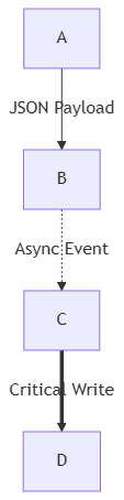
4. Modular Isolation via Subgraphs
To establish clean network perimeters, group microservices, or isolate team responsibilities, group your elements inside structuralsubgraph wrappers. You define a subgraph by giving it an internal ID, an optional display title, and closing it with an end tag:
Mermaid
Edit Mermaid in VPasCode
flowchart TD
    subgraph auth_sub["Security Boundary"]
        gateway[API Gateway] --> auth_worker(Token Validator)
    end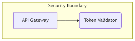
Best Practices for Clean Flowcharts
- Decouple Layouts Horizontally: For long, multi-step engineering pipelines, choose a
flowchart LRdirection. This scales much cleaner on standard widescreen landscape monitors than a long vertical layout. - Isolate Complex Loops: If a workflow contains a heavy repetition loop, label the reverse connector clearly (e.g.,
retry --> |"Attempt Reset"| start) to prevent readers from confusing the loop with a standard forward path. - Avoid Mixing Graph Types: Stick to the modern
flowchartkeyword over the legacygraphflag when rendering complex maps. Theflowchartengine uses an updated layout algorithm that supports advanced arrow combinations and cleaner path routing.
Real-World Mermaid.js Flowchart Examples
Example 1: Microservice Event-Driven Ingestion Mesh (Left-to-Right Architecture)
This functional blueprint models a web telemetry ingestion service. It demonstrates how to combine data inputs, decision diamonds, and cloud database shapes across a crisp horizontal canvas.
Mermaid
Edit Mermaid in VPasCode
flowchart LR
    %% Define element nodes with explicit geometry shapes
    init([Webhook Fired]) --> input_io[/Capture HTTP Request/]
    input_io --> auth_check{Validate Token}

    auth_check --> |"Invalid Token"| err_stop([Return 401 Unauthorized])
    auth_check --> |"Valid JWT"| write_queue[[Publish to Kafka Queue]]

    write_queue --> worker_proc(Consumer Daemon)
    worker_proc --> db_store[(TimescaleDB Cluster)]
    db_store --> term([Terminated Flow])

    %% Quick custom style overrides
    style auth_check fill:#fff3cd,stroke:#ffc107,stroke-width:2px
    style err_stop fill:#f8d7da,stroke:#dc3545,stroke-width:1px
auth_check{Validate Token}), which splits the execution path cleanly into two distinct outcomes. The data stores are instantly recognizable thanks to their custom database cylinders ([(TimescaleDB Cluster)]) and parallelogram inputs.
Example 2: Enterprise Multi-Tier User Registration Engine (Vertical with Nested Subgraphs)
This advanced enterprise blueprint maps out an application registration pipeline. It organizes steps vertically across three separate structural subgraphs to represent distinct architectural layers.
Mermaid
Edit Mermaid in VPasCode
flowchart TD
    subgraph Client_Tier["Presentation UI Layer"]
        app[Mobile App UI]
        web[Web SPA Frontend]
    end

    subgraph Service_Tier["Core Gateway Router"]
        proxy[[Nginx Ingress Reverse Proxy]]
        auth_svc(Auth Service Worker)
    end

    subgraph Persistence_Tier["Secured Data Center"]
        main_db[(User Accounts Primary DB)]
        cache_node[(Redis Session Cache)]
    end

    %% Define communication pipelines across subsystem layers
    app -- "HTTPS Request" --> proxy
    web -- "HTTPS Request" --> proxy

    proxy --> |"Route /v1/auth"| auth_svc

    auth_svc --> |"Verify Session"| cache_node
    auth_svc --> |"Commit Account"| main_db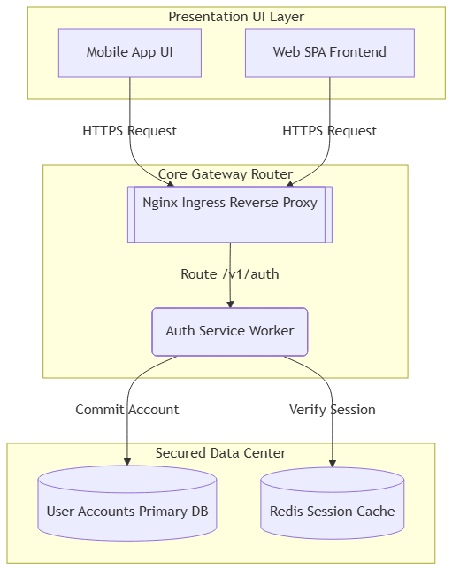
flowchart TD) forces the layout engine to stack components cleanly from top to bottom. Bounding blocks group related components into distinct layers (Client, Service, and Persistence), giving the overall architecture an intuitive, highly structured feel.