


What is the C4 Model Diagram?
The C4 Model Diagram is a hierarchical, four-level architectural framework designed to document software architecture with varying degrees of granular detail. Created by Simon Brown, C4 avoids vague boxes and lines by structuring system maps into four explicit abstraction lenses: Context (System-level scope), Container (Applications and data stores), Component (Internal modules), and Code (Class-level implementations). To implement this model effectively in text, engineers use the officialC4-PlantUML standard library extension. This library replaces raw UML shapes with specialized macros that auto-inject distinct colors, shapes, and metadata fields for users, systems, and databases. With VPasCode, you can define these nested environments cleanly in code. The layout engine dynamically routes connection vectors and scales text fields without ruining your layout geometry.
Core Syntax Guide: Elements and Constructs
Building a valid C4 model using PlantUML relies on importing the correct library files, selecting structural macros, establishing boundaries, and using specialized relationship links.1. Importing the C4 Standard Library Files
TheC4-PlantUML extension is broken up into individual files that map directly to the distinct levels of the abstraction model. To prevent performance slowdowns or compiler errors, you should only import the specific file layer your diagram targets:
PlantUML
Edit PlantUML in VPasCode
@startuml
' Include the specific C4 layer file required
!include <C4/C4_Context>
' Use C4_Container or C4_Component for deeper architectural maps2. Declaring Core Actors and Systems (Context Level)
At the high-level System Context tier, you model internal components, external dependencies, and human end-users. The standard library provides specific macros that accept an ID, a visual label, and an optional descriptive tag:Person(id, "Label", "Description")— Represents a human user profile or system actor.System(id, "Label", "Description")— Represents a primary internal software application or service ecosystem.System_Ext(id, "Label", "Description")— Represents an external system or third-party API dependency (renders in an explicit grey color palette).
PlantUML
Edit PlantUML in VPasCode
@startuml C4_Elements
!include <C4/C4_Context>
Person(customer, "Banking Customer", "A customer with a personal bank account")
System(banking_sys, "Core Banking System", "Handles financial transactions")
System_Ext(mail_sys, "E-mail Service", "Internal SMTP notification gateway")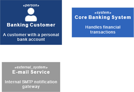
3. Exploding Boundaries (Container & Component Levels)
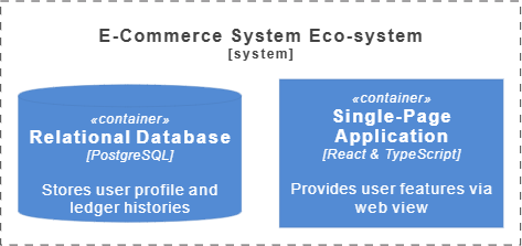
When diving deeper into the Container layer, you model web apps, microservices, and databases. You can isolate these internal elements inside an explicit logical boundary box using theSystem_Boundary() macro wrapper:
PlantUML
Edit PlantUML in VPasCode
!include <C4/C4_Container>

System_Boundary(c1, "E-Commerce System Eco-system") {
    Container(web_app, "Single-Page Application", "React & TypeScript", "Provides user features via web view")
    ContainerDb(database, "Relational Database", "PostgreSQL", "Stores user profile and ledger histories")
}
4. Mapping Technical Relationships
Instead of relying on basic dashed lines, C4 utilizes explicit communication macros format asRel(From_ID, To_ID, "Label", "Technology"). This keeps your architecture maps highly readable by enforcing that every connection states its purpose and underlying transport protocol (such as HTTPS, gRPC, or AMQP):
PlantUML
Edit PlantUML in VPasCode
!include <C4/C4_Container>

Person(customer, "Banking Customer", "A customer with a personal bank account")
System(banking_sys, "Core Banking System", "Handles financial transactions")
System_Ext(mail_sys, "E-mail Service", "Internal SMTP notification gateway")

System_Boundary(c1, "E-Commerce System Eco-system") {
    Container(web_app, "Single-Page Application", "React & TypeScript", "Provides user features via web view")
    ContainerDb(database, "Relational Database", "PostgreSQL", "Stores user profile and ledger histories")
}
Rel(customer, web_app, "Uses storefront features via", "HTTPS")
Rel(web_app, database, "Reads and writes transactional data via", "SQL/TCP")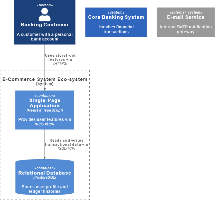
Best Practices for Readable C4 Architectures
- Never Mix Abstraction Levels: Keep your diagrams focused on a single layer. Do not mix fine-grained internal software components into a high-level System Context map. If a system gets too complex, break it out into a separate, dedicated Container-level diagram.
- Explicitly Define Technologies: Always make use of the fourth parameter in your
Rel()macros to state the exact technology or protocol being used (e.g.,"JSON/HTTPS"or"JDBC"). This gives your team crucial implementation context at a glance. - Leverage Directional Layout Overrides: If your components begin to stack up awkwardly, use directional relationship macros (like
Rel_D()for down,Rel_R()for right, orRel_L()for left) to manually clean up your architectural flow.
Real-World PlantUML C4 Examples
Example 1: High-Level System Context Layout (Level 1)
This functional blueprint models a standard Level 1 System Context diagram, detailing how a customer interacts with an internet banking application and its external dependencies.
PlantUML
Edit PlantUML in VPasCode
@startuml
!include <C4/C4_Context>

title System Context Diagram for Internet Banking System

Person(customer, "Personal Banking Customer", "A customer of the bank with personal accounts.")
System(banking_system, "Internet Banking System", "Allows customers to view financial info and make transfers.")
System_Ext(mail_system, "E-mail Subsystem", "The internal enterprise SendGrid corporate mail server cluster.")

Rel(customer, banking_system, "Uses online dashboard via")
Rel_R(banking_system, mail_system, "Sends alerts and verification codes using", "SMTP")
@enduml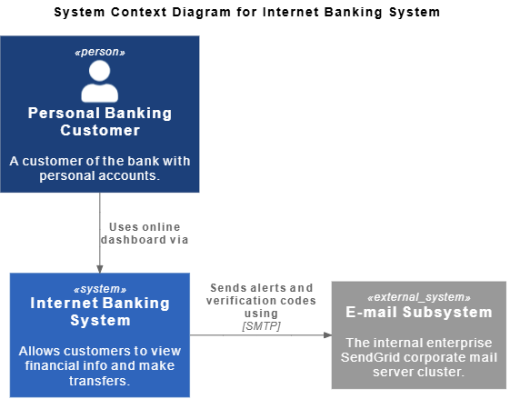
System_Ext macro automatically applies a grey color profile to the e-mail service, visually separating the core system from external dependencies. The Rel_R macro forces the layout engine to place the email node directly to the right of the banking system block.
Example 2: Deep-Dive Microservice Container Topology (Level 2)
This advanced enterprise blueprint breaks down a system into its constituent container applications and isolated data stores, showing how web traffic routes through an API gateway down to backend microservices.
PlantUML
Edit PlantUML in VPasCode
@startuml
!include <C4/C4_Container>

title Container Diagram for Payment Portal Gateway

Person(merchant, "Web Merchant Partner", "Integrates platform checkout endpoints into their websites.")

System_Boundary(portal_scope, "Payment Gateway Ecosystem") {
    Container(api_gateway, "API Routing Proxy", "Nginx", "Intercepts inbound calls, handles rate limits and balances nodes.")
    Container(auth_service, "Identity Microservice", "Go & OAuth2", "Validates developer API tokens and scopes.")
    Container(txn_service, "Transaction Ledger", "Java Spring Boot", "Processes payments and manages ledger accounts.")
    ContainerDb(ledger_db, "Ledger Datastore", "CockroachDB", "Implements distributed ACID-compliant table schemas.")
}

' Route traffic flows cleanly across internal container targets
Rel(merchant, api_gateway, "Submits payment payloads via", "HTTPS/JSON")
Rel_D(api_gateway, auth_service, "Validates incoming tokens via", "gRPC")
Rel_D(api_gateway, txn_service, "Forwards checkout actions to", "gRPC")
Rel_R(txn_service, ledger_db, "Persists ledger entries via", "SQL/TLS")
@enduml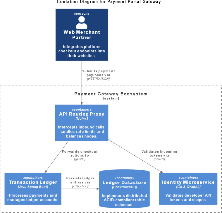
System_Boundary macro wrapper, internal components are cleanly grouped together inside a clear perimeter box. The specialized ContainerDb macro renders the data store with an explicit database cylinder icon, making the division between compute runtimes and persistent storage layers clear at a glance.