


What is a Deployment Diagram?
A Deployment Diagram is a structural UML diagram that models the physical execution architecture of a software system. As a core standard of the Unified Modeling Language (UML) specification, this specific UML diagram type maps out how software components are physically deployed onto hardware hosting targets, cloud infrastructure elements, or container runtimes. It provides system engineers, DevOps professionals, and network architects with a clear layout of server cluster boundaries, database replication paths, load balancer tiers, and hardware network protocols across development and production regions. With VPasCode, you don’t need to struggle with complex vector grouping shapes or manual coordinate mapping. By using plain declarative script blocks, our engine automatically groups, calculates, and nests your hardware node structures cleanly.Core Syntax Guide: Elements and Constructs
To design an accurate, standards-compliant UML deployment diagram in PlantUML, you need to master hardware nodes, execution environments, deployment artifacts, and network linkages.1. Declaring Infrastructure Cubes (Nodes)
In a deployment layout, physical computing resources are represented as 3D three-dimensional cubes. You declare these elements using thenode keyword, or by choosing specialized variants that give readers instant visual context about the hardware tier:
PlantUML
Edit PlantUML in VPasCode
node "Bare Metal Application Server" as CoreServer
node Server1
database "Database Server" as DB_Node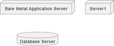
2. Modeling Cloud Layers and Virtual Environments
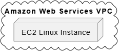
Modern applications are rarely deployed straight onto physical hardware. PlantUML provides nested grouping wrappers to represent logical execution boundaries, cloud provider footprints, or virtual container runtimes like Docker and Kubernetes:cloud— Represents external public web tiers or cloud network boundaries (e.g., AWS, Azure).frame— Represents virtual systems or organizational regions.storage— Represents physical SAN configurations or object store locations.
PlantUML
Edit PlantUML in VPasCode
cloud "Amazon Web Services VPC" {
    node "EC2 Linux Instance" as WorkerNode
}
3. Defining Deployment Artifacts (What Runs Where)
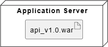
An artifact represents the actual physical file (such as a compiled JAR file, a static build folder, or a zipped package) that is deployed onto a node. You declare an artifact using theartifact keyword, or place it inside your hardware blocks directly:
PlantUML
Edit PlantUML in VPasCode
node "Application Server" {
    artifact "api_v1.0.war" as API_File
}
4. Mapping Network Communication Links
Connections between infrastructure elements represent concrete physical networks, wire paths, or wireless channels. You map these links using solid double dashes (--), and append text inside quotes to explicitly define the network protocol used (e.g., HTTPS, TCP/IP, SSH):
PlantUML
Edit PlantUML in VPasCode
node Server1
node DB_Node
Server1 -- DB_Node : "TCP/IP (Port 5432)"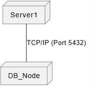
Best Practices for Practical Deployment Maps
- Nest Structures Correctly: Always draw your internal components or artifacts *inside* the curly brackets of your
nodedeclarations to clearly show execution residency. - Label Communication Protocols: Never draw a blank line between servers. Always label the connection with its primary communication protocol (e.g.,
"HTTPS (Port 443)") to help network and security reviews. - Isolate Availability Zones: When documenting high-availability cloud configurations, use separate
framewrappers to illustrate split region setups (e.g.,us-east-1avs.us-east-1b).
Real-World PlantUML Deployment Diagram Examples
Example 1: Classic Three-Tier Web Setup (Nodes & Protocols)
This boilerplate models a standard modern corporate application structure, mapping an external content distribution network, an application server cluster, and a secured internal database host tier.
PlantUML
Edit PlantUML in VPasCode
@startuml
cloud "Public Internet" as net

node "Cloudflare CDN Edge" as cdn

frame "Demilitarized Zone (DMZ)" {
    node "Nginx Load Balancer Server" as proxy
}

frame "Private Application VPC Subnet" {
    node "Ubuntu Server 22.04" as app_node {
        artifact "core_api.jar" as application
    }
}

database "Managed Database Tier" {
    node "PostgreSQL Primary Cluster" as db_master
}

' Establish topological connection wires
net -- cdn : "HTTPS"
cdn -- proxy : "HTTPS (TLS 1.3)"
proxy -- app_node : "HTTP (Port 8080)"
app_node -- db_master : "TCP/IP (Port 5432)"
@enduml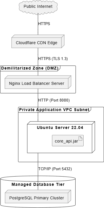
core_api.jar is nested safely inside the app_node server box. Network pathways scale cleanly inward, establishing strict protocol rules for every segment from the public web edge down to the managed database tier.
Example 2: Cloud-Native Container Architecture (Kubernetes & AWS Mesh)
This advanced enterprise blueprint maps a highly scalable, multi-region cloud deployment. It utilizes nested node layouts to visualize a load-balanced Kubernetes container system interacting with standalone cloud databases.
PlantUML
Edit PlantUML in VPasCode
@startuml
cloud "Amazon Web Services (AWS)" {

    node "AWS Application Load Balancer" as alb

    frame "Availability Zone: us-east-1a" {
        node "EC2 Worker Node Node A" as ec2_a {
            node "K8s Pod: Web Frontend" as pod_web_a
            node "K8s Pod: Order API" as pod_api_a
        }
    }

    frame "Availability Zone: us-east-1b" {
        node "EC2 Worker Node Node B" as ec2_b {
            node "K8s Pod: Web Frontend" as pod_web_b
            node "K8s Pod: Order API" as pod_api_b
        }
    }

    storage "AWS Aurora Serverless Clusters" {
        database "Customer Database" as rds_db
    }
}

' Route infrastructure orchestration lines
alb -- pod_web_a : "HTTP Round-Robin"
alb -- pod_web_b : "HTTP Round-Robin"

pod_web_a -- pod_api_a : "Internal gRPC"
pod_web_b -- pod_api_b : "Internal gRPC"

pod_api_a -- rds_db : "SSL/TCP"
pod_api_b -- rds_db : "SSL/TCP"
@enduml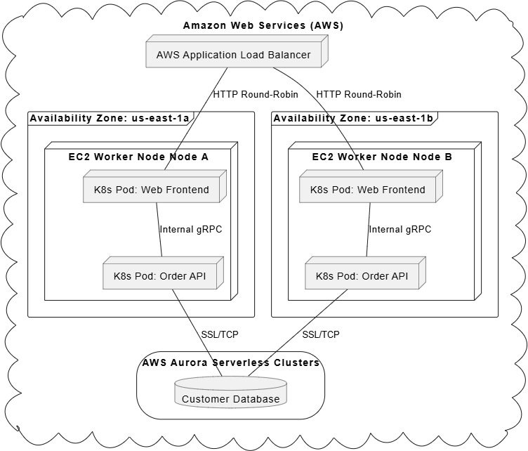
node targets within child node structures, this template models a containerized layout perfectly (Pods executing inside EC2 Virtual Machines). The application load balancer seamlessly distributes incoming requests across availability zones, while the cluster components route database calls back into a shared storage pool.