What is a Network Diagram?
A Network Diagram (powered by thenwdiag engine inside PlantUML) is an infrastructure architecture diagram used to visualize computer networks, IP subnets, server topologies, firewalls, and routing structures. It highlights how servers, cloud instances, and database nodes connect across physical or virtual network segments.
With VPasCode, you can write concise text scripts to build publication-ready network diagrams automatically. This eliminates manual shape snapping and wire routing on a visual canvas while keeping infrastructure layouts versionable alongside your code and deployment scripts.
Core Syntax Guide: Elements and Constructs
Building a Network Diagram in VPasCode uses network block definitions and node declarations wrapped inside standard@startnwdiag and @endnwdiag block boundaries.
1. Defining Subnets and Network Segments
Declare network segments using thenetwork block name, and specify subnet CIDR blocks or IP ranges using the address parameter:
PlantUML
Edit PlantUML in VPasCode
@startnwdiag
network DMZ {
  address = "210.x.x.x/24"
  web01;
  web02;
}
@endnwdiag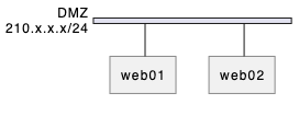
2. Assigning Node IP Addresses and Labels
Assign explicit IP addresses and human-readable labels to specific network nodes directly inside the network block:
PlantUML
Edit PlantUML in VPasCode
@startnwdiag
network Internal {
  address = "192.168.1.0/24"

  app01 [address = "192.168.1.10", description = "App Server 01"];
  db01  [address = "192.168.1.50", description = "Primary Database"];
}
@endnwdiag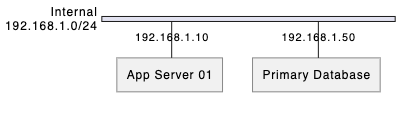
Pro Tip: Usingdescription = "Human Label"gives nodes readable names while keeping short variable keys (likeapp01ordb01) for cleaner script maintenance.
3. Multi-Homed Nodes (Connecting Across Subnets)
To connect a server or firewall across multiple network segments, simply declare the same node inside each correspondingnetwork block:
PlantUML
Edit PlantUML in VPasCode
@startnwdiag
network Public {
  address = "10.0.1.0/24"
  firewall [address = "10.0.1.1"];
}

network Private {
  address = "10.0.2.0/24"
  firewall [address = "10.0.2.1"];
  app_server [address = "10.0.2.10"];
}
@endnwdiag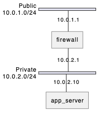
4. Grouping Nodes with Clusters
Group related servers (such as database clusters or load balancer pairs) visually using thegroup container construct:
PlantUML
Edit PlantUML in VPasCode
@startnwdiag
network Internal {
  db01;
  db02;
}

group DBCluster {
  color = "LightPink";
  description = "HA Database Cluster";
  db01;
  db02;
}
@endnwdiag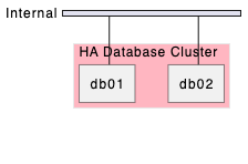
Best Practices for Clean Layouts
- Label Subnets Explicitly: Always supply an
address = "CIDR"parameter for each network block to clarify routing boundaries. - Reuse Node Keys for Routers/Firewalls: Declare dual-homed appliances across adjacent network blocks to automatically generate gateway bridging lines.
- Color-Code High Availability Groups: Use
groupcontainers with custom background colors to highlight load-balanced or clustered server pools.
Real-World PlantUML Network Diagram Examples
Copy and paste these blueprints directly into your VPasCode editor panel to see them render in real time.Example 1: Enterprise 3-Tier Web Application Topology
This blueprint models a classic enterprise multi-tier architecture spanning an External Internet segment, a DMZ Load Balancer layer, an Application Subnet, and an Isolated Database Subnet.
PlantUML
Edit PlantUML in VPasCode
@startnwdiag
network Internet {
  address = "0.0.0.0/0"
  user [shape = "actor", description = "External User"];
  router [address = "203.0.113.1", description = "Edge Router"];
}

network DMZ {
  address = "172.16.1.0/24"
  router [address = "172.16.1.1"];
  lb01 [address = "172.16.1.10", description = "Nginx Load Balancer"];
}

network AppSubnet {
  address = "10.0.1.0/24"
  lb01 [address = "10.0.1.1"];
  app01 [address = "10.0.1.11", description = "App Server 01"];
  app02 [address = "10.0.1.12", description = "App Server 02"];
}

network DBSubnet {
  address = "10.0.2.0/24"
  app01 [address = "10.0.2.1"];
  app02 [address = "10.0.2.1"];
  db_primary [address = "10.0.2.100", description = "PostgreSQL Primary"];
  db_replica [address = "10.0.2.101", description = "PostgreSQL Replica"];
}

group DatabaseGroup {
  color = "LightCyan"
  description = "Replicated DB Pair"
  db_primary;
  db_replica;
}
@endnwdiag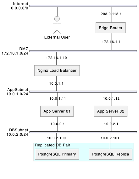
group cluster container.
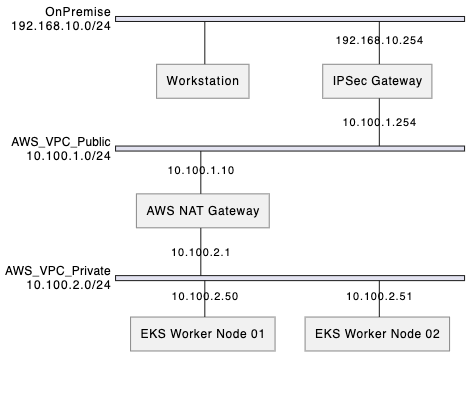
Example 2: Hybrid Cloud VPN Network Infrastructure
This blueprint structures a secure hybrid cloud connection linking an On-Premise Corporate Network to an AWS Virtual Private Cloud (VPC) via a VPN Gateway.
PlantUML
Edit PlantUML in VPasCode
@startnwdiag
network OnPremise {
  address = "192.168.10.0/24"
  office_pc [description = "Workstation"];
  vpn_appliance [address = "192.168.10.254", description = "IPSec Gateway"];
}

network AWS_VPC_Public {
  address = "10.100.1.0/24"
  vpn_appliance [address = "10.100.1.254"];
  nat_gateway [address = "10.100.1.10", description = "AWS NAT Gateway"];
}

network AWS_VPC_Private {
  address = "10.100.2.0/24"
  nat_gateway [address = "10.100.2.1"];
  k8s_worker1 [address = "10.100.2.50", description = "EKS Worker Node 01"];
  k8s_worker2 [address = "10.100.2.51", description = "EKS Worker Node 02"];
}
@endnwdiag