


Note: You can set the layout direction using
direction: right or direction: down at the top of your D2 code block.1. System Architecture Diagram
A multi-tier cloud web architecture featuring nested servers and storage components.direction: right
User: {
shape: person
}
Web Application: {
CDN: {
shape: cloud
}
Load Balancer
App Servers: {
Server 1
Server 2
}
Data Tier: {
PostgreSQL Database: {
shape: cylinder
}
Redis Cache: {
shape: cylinder
}
}
}
User -> Web Application.CDN: Requests Page
Web Application.CDN -> Web Application.Load Balancer: Route Traffic
Web Application.Load Balancer -> Web Application.App Servers.Server 1
Web Application.Load Balancer -> Web Application.App Servers.Server 2
Web Application.App Servers.Server 1 -> Web Application.Data Tier.Redis Cache: Check Cache
Web Application.App Servers.Server 1 -> Web Application.Data Tier.PostgreSQL Database: Query Data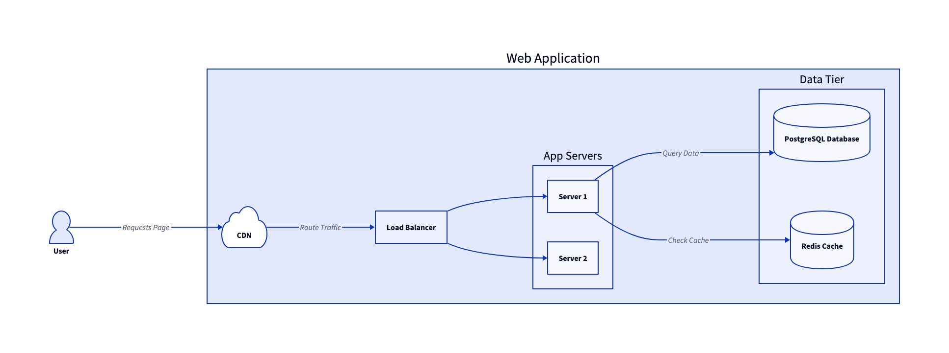
2. Database Schema (SQL Table Diagram)
D2 features built-in support for rendering SQL tables and entity relationships cleanly using thesql_table shape.
users: {
  shape: sql_table
  id: int {constraint: primary_key}
  username: varchar
  email: varchar
  created_at: timestamp
}

orders: {
  shape: sql_table
  id: int {constraint: primary_key}
  user_id: int {constraint: foreign_key}
  total_amount: decimal
  status: varchar
}

order_items: {
  shape: sql_table
  id: int {constraint: primary_key}
  order_id: int {constraint: foreign_key}
  product_name: varchar
  quantity: int
}

users.id -> orders.user_id: 1-to-Many
orders.id -> order_items.order_id: 1-to-Many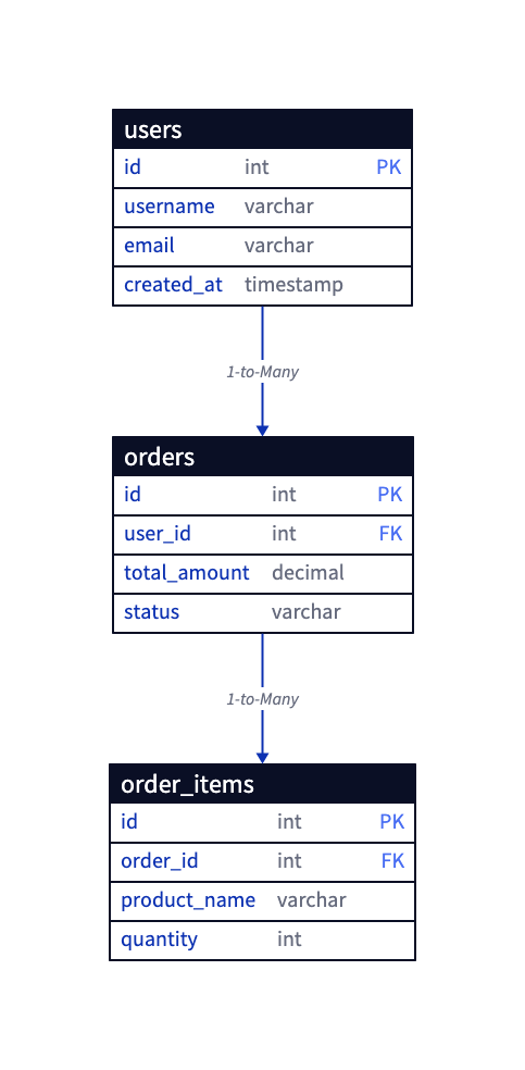
3. Automated Deployment Pipeline (CI/CD)
Map out software deployment steps from code check-in to live production release.direction: right
Developer -> GitHub: 1. Push Code
GitHub Pipelines: {
Build Step -> Test Step -> Docker Image
}
GitHub -> GitHub Pipelines: 2. Trigger Action
GitHub Pipelines.Docker Image -> Docker Registry: 3. Store Build
Docker Registry -> Production Server: 4. Deploy Container