


What is a Communication Diagram?
A UML Communication Diagram (formerly known as a Collaboration Diagram) is an interaction diagram that illustrates how objects and system participants co-operate to perform complex workflows. Unlike standard Sequence Diagrams, Communication Diagrams focus on the structural relationships and message paths between components. With VPasCode, you can write concise PlantUML scripts to build publication-ready communication diagrams with numbered sequence calls and color-coded message tracing, eliminating manual shape positioning on a canvas.Core Syntax Guide: Elements and Constructs
Building a Communication Diagram in VPasCode uses object declarations and message links written inside standard@startuml and @enduml tags, using VPasCode’s communication diagram theme settings.
1. Declaring Participants and Objects
To define participating components, services, or users in your interaction flow, declare objects using standardobject syntax:
PlantUML
Edit PlantUML in VPasCode
object "Customer" as customer
object "ATM Terminal" as atm
object "Bank Core System" as bank
object "Account Database" as db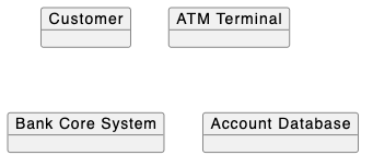
Pro Tip: Setting custom object aliases (e.g., as atm) keeps your message link definitions clean and readable.
2. Modeling Message Flows and Sequence Numbers
Connect objects using solid links (-) and annotate interactions with sequence numbers and directional arrows (▶ for outbound calls or ◀ for return responses):
PlantUML
Edit PlantUML in VPasCode
customer - atm : ▶ 1: insertCardAndPin()\n◀ 1a: promptAmount()
atm - bank : ▶ 2: requestAuthentication()\n◀ 2a: returnAuthOk()
bank - db : ▶ 3: validatePinAndAccount()\n◀ 3a: accountValid()
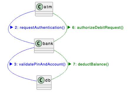
3. Visual Tracing with Color-Coded Message Links
When orchestrating multi-party interactions across several microservices, assign distinct color parameters directly to connection links (e.g.,-[#blue]- or -[#green]-) and wrap text in matching <color:name> tags to visually group execution paths:
atm -[#blue]- bank : <color:blue>▶ 2: requestAuthentication()</color>
bank -[#blue]- db : <color:blue>▶ 3: validatePinAndAccount()</color>
atm -[#green]- bank : <color:green>▶ 6: authorizeDebitRequest()</color>
bank -[#green]- db : <color:green>▶ 7: deductBalance()</color>
4. Controlling Element Layout and Spacing
Short object names likeUser or DB can result in tiny, cramped boxes. Use skin parameters at the top of your script to adjust element spacing and spacing between nodes for a balanced layout:
PlantUML
Edit PlantUML in VPasCode
@startuml
!include https://static.visual-paradigm.com/web/resources/plantuml-stdlib/themes/vp.puml
skinparam {
  vpDiagramType CommunicationDiagram
  nodesep 80
}

title Simple Login Flow

object "User" as user
object "Auth Service" as auth

user - auth : ▶ 1: login(credentials)\n◀ 1a: tokenResponse
@enduml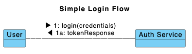
Key Layout Options:
nodesep 80: Controls horizontal separation space between objects to prevent overlapping text labels.ranksep 80: Controls vertical separation distance between object tiers.
Best Practices for Clean Layouts
- Include Theme & Diagram Type: Always include the VPasCode theme file and set
vpDiagramType CommunicationDiagraminside theskinparamblock. - Set Minimum Object Widths: Include
MinimumWidth 80inside a<style>block to maintain uniform shape sizing. - Use Sequential Numbering & Direction Markers: Number every message sequentially (
1:,2:,3:) and use▶/◀to indicate request and response direction. - Use Color Grouping: Group related request-response phases with matching line and text colors (e.g., Blue for authentication, Green for transaction execution).
Real-World PlantUML Communication Diagram Examples
Copy and paste these blueprints directly into your VPasCode editor panel to see them render in real time.Example 1: ATM Cash Withdrawal Communication Flow
This blueprint maps a complete cash withdrawal transaction across a Customer, ATM Interface, Central Banking Core, and Account Database.
PlantUML
Edit PlantUML in VPasCode
@startuml
skinparam {
  vpDiagramType CommunicationDiagram
  nodesep 80
}

<style>
object {
  MinimumWidth 80
}
</style>

left to right direction

title ATM Cash Withdrawal Communication Flow

object "Customer" as customer
object "ATM Terminal" as atm
object "Bank Core System" as bank
object "Account Database" as db

customer - atm : ▶ 1: insertCardAndPin()\n◀ 1a: promptAmount()\n▶ 5: enterWithdrawalAmount()\n◀ 5a: dispenseCashAndReceipt()

atm -[#blue]- bank : <color:blue>▶ 2: requestAuthentication()</color>\n<color:blue>◀ 2a: returnAuthOk()</color>

bank -[#blue]- db : <color:blue>▶ 3: validatePinAndAccount()</color>\n<color:blue>◀ 3a: accountValid()</color>

atm -[#green]- bank : <color:green>▶ 6: authorizeDebitRequest()</color>\n<color:green>◀ 6a: dispenseSignal()</color>

bank -[#green]- db : <color:green>▶ 7: deductBalance()</color>\n<color:green>◀ 7a: balanceUpdated()</color>

@enduml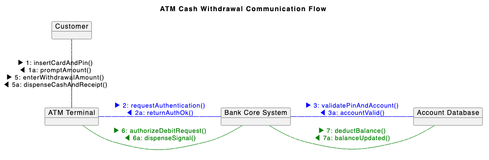
object declarations along with color-coded message links (-[#blue]- for authentication and -[#green]- for transaction debit) to track the step-by-step communication lifecycle.
Example 2: Remote Patient Consultation Scheduling
This blueprint models a multi-party consultation scheduling system across a patient portal, scheduling service, directory service, notification engine, and telehealth platform.
PlantUML
Edit PlantUML in VPasCode
@startuml
!include https://static.visual-paradigm.com/web/resources/plantuml-stdlib/themes/vp.puml
skinparam {
  vpDiagramType CommunicationDiagram
  nodesep 80
}

<style>
object {
  MinimumWidth 80
}
</style>

left to right direction

title Remote Patient Consultation Scheduling

object "Patient" as Patient
object "Patient Portal" as Portal
object "Scheduling Service" as Scheduler
object "Provider Directory" as Directory
object "Notification Service" as Notifier
object "Telehealth Platform" as Telehealth
object "Clinician" as Clinician

Patient -[#blue]- Portal : <color:blue>▶ 1: requestConsultation(specialty, preferredDate)</color>\n<color:blue>◀ 1a: showAvailableSlots(slotList)</color>\n<color:blue>▶ 6: confirmBooking(slotId)</color>\n<color:blue>◀ 6a: bookingConfirmed(appointmentRef, joinLink)</color>

Portal -[#green]- Scheduler : <color:green>▶ 2: findAvailableSlots(specialty, dateRange)</color>\n<color:green>◀ 2a: slotList</color>\n<color:green>▶ 7: createAppointment(patientId, slotId)</color>\n<color:green>◀ 7a: appointmentRef, joinLink</color>

Scheduler -[#orange]- Directory : <color:orange>▶ 3: queryProviderAvailability(specialty)</color>\n<color:orange>◀ 3a: clinicianList, availableWindows</color>

Scheduler -[#purple]- Notifier : <color:purple>▶ 4: notifyPatient(availableSlotAlert)</color>\n<color:purple>◀ 4a: alertDelivered</color>\n<color:purple>▶ 8: sendAppointmentConfirmation(appointmentRef)</color>\n<color:purple>◀ 8a: confirmationSent</color>

Scheduler -[#red]- Telehealth : <color:red>▶ 9: provisionVirtualRoom(appointmentRef)</color>\n<color:red>◀ 9a: sessionUrl, accessCode</color>

Telehealth -[#brown]- Clinician : <color:brown>▶ 10: notifyClinician(sessionDetails)</color>\n<color:brown>◀ 10a: sessionAcknowledged</color>

@enduml
1: through 10:) combined with distinct link colors isolates separate sub-system calls while preserving the structural relationship between actors and backend services.